PCAN-Dongle (ISO) Adapter PC Parallel Port to High-speed CAN User Manual
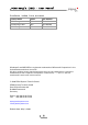
PCAN-Dongle (ISO) – User Manual Products taken into account Product Name Model Item Number PCAN-Dongle PS/2 IPEH-002019 PCAN-Dongle ISO PS/2 IPEH-002020 PCAN-Dongle DIN IPEH-002015 Windows® and MS-DOS are registered trademarks of Microsoft Corporation in the United States and other countries. All other product names mentioned herein may be the trademarks or registered trademarks of their respective companies. Furthermore, "™" and "®" are not mentioned in each case in this manual.
PCAN-Dongle (ISO) – User Manual Contents 1 1.1 1.2 1.3 2 2.1 2.2 2.3 3 3.1 3.2 4 4.1 4.
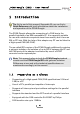
PCAN-Dongle (ISO) – User Manual 1 Introduction Tip: At the end of this manual (Appendix B) you can find a Quick Reference with brief information about the installation and operation of the PCAN-Dongle. The PCAN-Dongle allows the connection of a CAN bus to the parallel interface of an IBM compatible PC. It is especially suitable for use with notebook computers since these usually don't have an ISA or PCI slot. With the help of this adapter any PC can be linked to a High-speed CAN (HS-CAN).
PCAN-Dongle (ISO) – User Manual CAN connection 9-pin Sub-D male, pin assignment according to CiA recommendation DS102 Galvanic isolation up to 500 V for the CAN interface (only PCANDongle ISO) Power supply (5 V) via cable with T-piece for keyboard connector (DIN or PS/2) Support for operating systems Windows (98 SE, ME, 2000 SP4, XP), Linux, and DOS Note: This manual describes the use of the PCAN-Dongle with Windows and DOS.
PCAN-Dongle (ISO) – User Manual 2 Hardware Installation 2.1 Connecting to the PC 1. Make sure that the PC is turned off. 2. Connect the PCAN-Dongle with the wider port (25 pins) to the free parallel port at the PC. 3. Pull the keyboard connector from the corresponding port at the PC. 4. Connect the T-piece at the cable of the PCAN-Dongle to the keyboard port. 5. Now reconnect the keyboard to the free end of the T-piece. A configuration of the hardware is not needed.
PCAN-Dongle (ISO) – User Manual First Test After turning on the PC the red LED at the PCAN-Dongle must be permanently on. This indicates that the power supply for the PCANDongle is correct. Attention! Don't remove PCAN-Dongle from the PC while powered on (red LED on PCAN-Dongle is lit). Electronic parts of the PCAN-Dongle or the PC's parallel interface may be harmed. 2.2 Connecting a HS-CAN A CAN is connected to the 9-pin Sub-D port on the PCAN-Dongle.
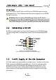
PCAN-Dongle (ISO) – User Manual When using this option, the 5-Volt supply is directly connected to the power supply of the PCAN-Dongle (coming from the PC) and is not fused separately. The ISO version of the Dongle contains an interconnected DC/DC converter. Therefore the current output is limited to about 50 mA. Attention! At this procedure a special care is indispensable since there is a short circuit danger.
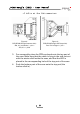
PCAN-Dongle (ISO) – User Manual +5 Volts at the CAN connector: Figure 2: PCB PCAN-Dongle (bottom side): JP9, 2-1 (as shown) → pin 1 JP9, 2-3 → pin 9 Figure 3: PCB PCAN-Dongle ISO (top side): Pos. R11 bridged → pin 1 3. For reassembly place the PCB overhead onto the top part of the case. Make sure that the cable is lying in the side cut-out with the strain relief inside the case, and that the LED is placed in the corresponding hole of the top part of the case. 4.
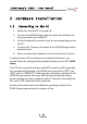
PCAN-Dongle (ISO) – User Manual 3 Software Setup This chapter describes the installation of the delivered software. You get to know more about its use in the following chapter 4. 3.1 Windows Operating Systems Under Windows a driver is needed that can access the PCANDongle and that provides the interface for Windows software. Beside the mentioned device driver the CAN monitor PCAN-View for Windows can also set up. Note: The following instructions are valid only for Windows 2000 and Windows XP.
PCAN-Dongle (ISO) – User Manual 3.2 DOS and Relatives You can find the CAN monitor PCAN-View for DOS and the programming samples in C and Pascal on the supplied CD-ROM in the following directories: PCAN-View for DOS: \Tools\PcanView\Dos Programming samples: \Develop\Dos\Dongle A separate setup procedure isn't needed.
PCAN-Dongle (ISO) – User Manual 4 Use The PCAN-Dongle can be used in one of four possible operating modes: Name of Operating Mode Alternative Identifier Description Multiplex Mode PEAK DongleCAN Standard Parallel Port (SPP) EPP Mode PEAK DongleCAN EPP Extended Capability Port (ECP) Multiplex PeliCAN PEAK DongleMode CAN SJA Standard Parallel Port (SPP), extended CAN functionality (CAN 2.0B incl. 29-bit IDs) EPP PeliCAN Mode Extended Capability Port (ECP), extended CAN functionality (CAN 2.
PCAN-Dongle (ISO) – User Manual 4.1 4.1.1 Getting Started under Windows Information about the Parallel Interface You need information about the used interrupt and port address of the parallel interface. It can be gained from the Device Manager of Windows: 1. On the desktop open the context menu of the icon "My Computer" (right mouse click) and select the command Properties. 2. Windows 2000, XP: Select the tab Hardware and click on the button Device Manager afterwards.
PCAN-Dongle (ISO) – User Manual Figure 4: Selection of the CAN specific parameters If no entry is in the list "Available CAN hardware" (for example at the first program start), you need to add one: 1. Press the button Add. The dialog box "Add CAN hardware" appears. 2. Select the connected hardware and the operating mode from the list "Type of CAN hardware". If the mode of the parallel interface is set to ECP in the PC's BIOS setup, you can register the PCAN-Dongle as "PEAK Dongle-CAN SJA EPP".
PCAN-Dongle (ISO) – User Manual Figure 5: Selection of hardware resources 3. Enter the port address and the interrupt of the used parallel interface established before (see section above). 4. Confirm your input with OK. In the dialog box "Connect to CAN hardware" make further settings (baud rate and CAN message filter) for the created hardware entry. If you need further help after the program start, use the online help provided with the program (key [F1]). 4.2 4.2.
PCAN-Dongle (ISO) – User Manual Port Address Interrupt LPT1 0x378 IRQ7 LPT2 0x278 IRQ5 LPT3 0x3BC IRQ5/7 4.2.2 PCAN-View for DOS The program PCAN-View for DOS enclosed in the package is a CAN monitor that supports various SJA1000/82C200 based PC hardware extensions by PEAK-System. It is able to transmit and receive CAN messages. As software with basic features it represents the Light version of CANMON for DOS. With PCAN-View for DOS you can examine existing nets and set up new ones.
PCAN-Dongle (ISO) – User Manual If the error message "CAN Controller 82C200 not found" is displayed, then double-check the used interrupt and port address as well as the selected hardware type. You can access the online help any time by pressing [F1].
PCAN-Dongle (ISO) – User Manual 5 Linking Own Programs with PCAN-Light On the supplied CD-ROM you can find files that are provided for software development. You can access them with the navigation program (button Programming). The files exclusively serve the linking of own programs to hardware by PEAK-System with the help of the installed device driver under Windows. Further more the CD-ROM contains header files and examples for creating own applications in conjunction with the Light drivers.
PCAN-Dongle (ISO) – User Manual 6 Frequently Asked Questions (FAQ) Question Answer In the PC's BIOS setup the parallel port setting shows ECP but the PCAN-Dongle works with the EPP mode. Is this correct? Yes, it is. The naming of the operating mode EPP of the PCANDongle has historical causes. The parallel interface at the PC went through various developments in the nineties. Only the EPP extension existed during the time, when the PCAN-Dongle arose. With version 1.
PCAN-Dongle (ISO) – User Manual 7 Technical Specifications Supply Supply voltage +5 V DC Current consumption max. 80 mA, PCAN-Dongle ISO max. 140 mA Connectors Supply Cable to the keyboard jack of the PC, length about 50 cm/20 inches PC Sub-D (m), 25 pins (to standard parallel port) CAN Sub-D (m), 9 pins Pin assignment according to CiA recommendation DS 102-1 PCAN-Dongle ISO: galvanic isolation up to 500 V CAN Specification ISO 11898 High-speed CAN (up to 1 MBit/s) 2.
PCAN-Dongle (ISO) – User Manual Appendix A A.
PCAN-Dongle (ISO) – User Manual 22
PCAN-Dongle (ISO) – User Manual Appendix B Quick Reference Hardware Installation Connect the PCAN-Dongle to the PC's parallel port, insert the Tpiece at the cable's end between the keyboard port at the PC and the keyboard connector (for power supply). When the PC is turned on, the red LED indicates an existing power supply. Software installation and startup under Windows Execute the driver installation program from the supplied CD-ROM. Restart Windows after the installation procedure.