
User Manual


5.2. Preliminary checks
If the battery symbol is shown on the LCD, then replace the
batteries with new 8 alkalines batteries (AA) before proceeding.
Check the current regulation:
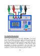
1. Connect the current leads to C
1
and C
2
.
2. Select a range, and short the current test leads. The R
C
LED
should go off, indicating that the current regulation is ok.
Check the voltage measurement:
1. Connect the potential leads to P
1
and P
2
.
2. Short the P
1
and P
2
. The display should indicate 000.
3. Remove the short from P
1
and P
2
and C
1
and C
2
. The R
P
LED should lit, indicating an over-voltage or over-range.
This proving test can be repeated on all the ranges if needed.
You can also check the polarity indication of the milli-voltmeter
by touching the potential test leads P
1
to C
2
and P
2
to C
1
. The R
P
LED should not lit, indicating an over-voltage or over-range.
The “-“ indicator should be indicating “-“ on the LCD, showing the
polarity change.
Total check can be done by shorting all the test leads together
C
1
, C
2
, P
1
, P
2
. The display should indicate close to 000
(depending of the crocodile clips used and how they are
shorted). Both R
C
and R
P
LED should be OFF, indicating, that
everything works okay.
5.3. Precautions
* Always ensure, that the circuit to be measured is switched
“OFF”, isolated and completely de-energised before
connecting the test leads.
-23-