Table of Contents 1. General Safety Requirements.................................................................................... 1 2. Safety Terms and Symbols ........................................................................................ 2 3. Quick Start ............................................................................................................... 3 3.1 Front/Rear Panel and User Interface .............................................................................. 3 3.1.
4.8 System Info ..................................................................................................................18 4.8.1 View System Information .............................................................................................................. 18 4.8.2 Set as Default................................................................................................................................. 18 4.8.3 Update .....................................................................
1.General Safety Requirements 1. General Safety Requirements Before use, please read the following safety precautions to avoid any possible bodily injury and to prevent this product or any other connected products from damage. To avoid any contingent danger, ensure this product is only used within the ranges specified. Only a qualified person should perform internal maintenance. To avoid Fire or Personal Injury: Use Proper Power Cord.
2.Safety Terms and Symbols 2. Safety Terms and Symbols Safety Terms Terms in this manual (The following terms may appear in this manual): Warning: Warning indicates conditions or practices that could result in injury or loss of life. Caution: Caution indicates the conditions or practices that could result in damage to this product or other property. Terms on the product. The following terms may appear on this product: Danger: Indicates an immediate hazard or injury possibility.
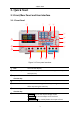
3.Quick Start 3. Quick Start 3.1 Front/Rear Panel and User Interface 3.1.1 Front Panel ② ① ③ ④ ⑤ ⑥ ⑮ ⑦ ⑭ ⑧ ⑬ ⑫ ⑪ ⑩ ⑨ Figure 3-1 Front panel overview ① LCD User interface display ② Numeric keys area Parameter input, includes the numeric keys, decimal point and backspace key.
3.Quick Start ⑧ CH2 control area Blue Volt/CV key: Set the output voltage of CH2 Blue Curr/CC key: Set the output current of CH2 Blue ON/OFF key: Enable/disable the output of CH2 ⑨ CH2 output terminals Channel 2 output connectors ⑩ MODE key Switch between All Channel mode (CH1 & CH2 & CH3) and Dual Channel Mode (CH1 & CH2).
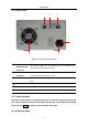
3.Quick Start 3.1.2 Rear Panel ① ② ③ ④ ⑥ ⑤ Figure 3-2 Rear panel overview ① Local Area Network (LAN) Connector The power supply can be connected to the network for remote control via this connector. ② USB Device Connector Connect as a "slave device" with an external USB device, such as connect the instrument to a PC. ③ COM Connector Connect the power supply with external equipment as serial port. ④ Power socket AC input connector ⑤ Fuse Line fuse ⑥ Fan Fan inlet 3.1.
3.Quick Start CV: Constant Voltage output CC: Constant Current output Channel 2 Channel 1 Mode icon Actual power output Actual voltage output Status icons Actual current output Set values of voltage Set values of current Set values of O.V.P/O.C.
3.Quick Start Status Icons Icons Instruction Connected to the network via LAN connector Connected as a slave device with PC A USB device is connected Recording the current output The panel keys are locked The beeper is turned on 3.2 General Inspection When you receive your new power supply, it is recommended that you check the instrument following these steps: 1. Check for transportation damage.
3.Quick Start (2) Push the power button on the front panel, the keys will light and the screen will show the boot screen. 3.4 Output Inspection Output inspection is to ensure that the instrument can achieve its rated outputs and properly respond to operation from the front panel. For the procedures below, it is suggested that you read "Turn On/Off the Channel Output" on page 9 and "Set the Output Voltage/Current" on page 9. 3.4.
4.Front Panel Operation 4. Front Panel Operation 4.1 Turn On/Off the Channel Output Press the orange ON/OFF key to turn on/off the Channel 1 output. Press the blue ON/OFF key to turn on/off the Channel 2 output. Press the ON/OFF CH3 key to turn on/off the Channel 3 output. 4.2 Set the Output Voltage/Current 4.2.1 Set the Output Voltage Set the output voltage of CH1 Press the orange Volt/CV key, the first digit of the CH1 set voltage is flashing, indicating the value is editable.
4.Front Panel Operation Press the blue Curr/CC key to enter edit mode. You can set the value in the same way as CH1 above. Set the output current of CH3 Press the Curr CH3 key to enter edit mode. You can set the value in the same way as CH1 above. Note: If the input value is out of the rated range, the box prompts "ERROR"; you need to input another value within the rated range. 4.3 Over Voltage/Current Protection When the Over Voltage Protection (O.V.P) or Over Current Protection (O.C.
4.Front Panel Operation Press the orange Curr/CC key, the first digit of the CH1 set current is flashing. Press the ▼ key, the first digit of the CH1 O.C.P is flashing, indicating the value is editable. There are two methods to change the value. Modify: Turn the knob to change the value. Press the < / > key to move the cursor. Press the knob or the key to confirm. Input: Use the numeric keys to input, the input box of Channel 1 limit current will pop up. Enter a desired value. Press the key to confirm.
4.Front Panel Operation (3) Press the ▼ key to select Stop Point submenu. Use the numeric keys to input (1 to 100), press the key to confirm. (4) Press the ▼ key to select Start submenu. Press the < / > key to select the channel (CH1, CH2 or ALL), press the and output the selected channel. key to enter the data processing interface 4.4.3 Data process You can set the programmable parameters of CH1 and CH2, including voltage, current and output time.
4.Front Panel Operation displayed in the chart in the data processing interface. (3) Press ← to back to sub menu selection. 4.4.4 Turn On/Off Programmable Output In the data processing interface: Independent Mode Press orange ON/OFF key to turn on/off the programmable output of Channel 1. Press blue ON/OFF key to turn on/off the programmable output of Channel 2. Parallel/Series Mode Press orange ON/OFF key to turn on/off the programmable output.
4.Front Panel Operation sub menu selection. (4) Press the ▼ key to select Recall submenu. Press the key, a red box will show in the table, indicating the selected item. Press the ▲ / ▼ key to select. Press the < / > key to turn the page. Press the key to recall. Press ← to back to sub menu selection. 4.5.2 Auto Record Press the Record key, turn the knob to select [Auto Record]. (1) The Memory sub menu is selected. Press the < / > key to select Internal or External.
4.Front Panel Operation the < / > key to select the channel (CH1, CH2 or CH3), press the key to read the recording file of the selected channel. After reading successfully, if the display mode is set as Table, a red box will show in the table, indicating you can press the < / > key to turn the page. Press ← to back to sub menu selection. When the Memory is set as External, press the ▲ key to select Export submenu.
4.Front Panel Operation is only for CH1 and CH2, without affecting CH3. There are four output modes: Independent Output The parameter of each channel can be set independently. Parallel track When CH1 and CH2 are connected in parallel, you can select this mode to simplify the parameter inputting. You just need to set the parameters of the combined channel. The voltage rating is same as the single channel; the current rating is the sum of CH1 and CH2 current rating.
4.Front Panel Operation CH1 and CH2 in series Series CH3 The connection method of the series connection of CH1 and CH2 is as shown in the figure below. POWER SUPPLY CH1 - CH2 + - V1 + V2 - VL + VL = V1 + V2 RL Channel track In independent output mode, set the output parameters of CH1 and CH2, and then enter the channel track mode, if the parameters of any one channel are changed, the other channel will change proportionally.
4.Front Panel Operation 4.7 Utility Settings 4.7.1 Language Press the Utility key, turn the knob to select [Utility]. The Language sub menu is selected. Press the < / > key to choose the desired language. The supported languages include: Chinese, English and so on. 4.7.2 Brightness Press the Utility key, turn the knob to select [Utility]. Press the ▼ key to select Brightness submenu. Press the < / > key to adjust the screen brightness. The brightness can be set to 0%, 25%, 50%, 75%, 100%. 4.7.
4.Front Panel Operation Limit settings Output CH1 CH2 CH3 Parallel Series VOLT CURR MAXOUT+1V MAXOUT+0.1A MAXOUT+1V 2*(MAXOUT+1V) 2*(MAXOUT+0.1A) MAXOUT+0.1A Output mode Brightness Beeper Serial Utility Port LAN Set Save Settings Record Auto Record View Record Independent mode 50% On Baud 115200 Data Bits 8 Odd-Even None Stop Bits 1 IP 192.168.001.099 Subnet Mask 255.255.255.000 Gateway 192.168.001.
4.Front Panel Operation 4.9 Port Settings 4.9.1 Serial port Press the Utility key, turn the knob to select [Port Set]. The Serial sub menu is selected. (1) Press the key to enter sub menu. The Baud is selected. Press the < / > key to select the desired baud rate from 1200, 2400, 4800, 9600, 19200, 38400, 57600 or 115200. The default is 115200. Make sure that the baud rate matches that of the computer. (2) Press the ▼ key to select Data Bits. Press the < / > key to select 6, 7, or 8.
5.Troubleshooting 5. Troubleshooting 1. The instrument is powered on but no Display. Check if the power is connected properly. Check if the fuse which is below the AC Power socket is used appropriately and in good condition (the cover can be pried open with a straight screwdriver). Restart the instrument after the steps above. If the problem still exists, please contact PeakTech for our service. 2. The output is abnormal: Check if the output voltage is set to 0V.
6.Appendix Options: Banana plug to crocodile clip test leads 6.2 Appendix B: General Care and Cleaning General Care Do not store or leave the instrument where the liquid crystal display could be exposed to direct sunlight for long periods of time. Caution: To avoid any damage to the instrument, do not exposed it to any sprays, liquids, or solvents. Cleaning Inspect the instrument as often as operating conditions require. To clean the instrument exterior, perform the following steps: 1.