Cover for Classic® 400 1
Intended to alert the user to the presence of uninsulated "dangerous voltage" within the product's enclosure that may be of sufficient magnitude to constitute a risk of electric shock to persons. Intended to alert the user of the presence of important operating and maintenance (servicing) instructions in the literature accompanying the product. CAUTION: Risk of electrical shock – DO NOT OPEN! CAUTION: To reduce the risk of electric shock, do not remove cover. No user serviceable parts inside.
ENGLISH 1 2 3 4 5 6 7 8 10 9 12 14 15 11 13 16 18 17 19 21 20 22 24 25 26 27 23 Classic® 400 Features • All-tube preamp and power amp • Eight 6550 power tubes • Five 12AX7s and one 12AT7 • Patented DDT™ power amp compression (defeated with push button) • No solid state devices in signal path • Two channels with separate EQ • Remote channel switching and combining • Remote switchable effects loop • Resonance and presence controls • Transformer balanced XLR jack • Push button selecta
Note: Channel selection may also be accomplished by the remote footswitch. If the remote selection is desired, the select switch must be in the “out” position. CHANNEL COMBINE SWITCH (4) Allows selection of single channel or combined channel operation. The “in” position of the switch selects combined channel operation where both channels operate simultaneously. The “out” position selects single channel operation. CLEAN CHANNEL INDICATOR (5) Illuminates green when channel is activated.
POST GAIN SWITCH — CRUNCH CHANNEL (21) Controls the overall volume level of the Crunch channel. The final level adjustment should be made after the desired sound has been achieved. DDT™ INDICATOR (22) Illuminates yellow LED when DDT Compression is taking place. DDT™ DEFEAT SWITCH (23) DDT power amp compression is defeated when the button is in the “in” position. Note: When DDT is defeated there is a greater chance of loudspeaker damage since power amplifier clipping can occur.
GROUND POLARITY SWITCH (30) Three-position, rocker-type switch which, in most applications, should be operated in its center (zero) position. There may be some situations when audible hum and/or noise will come from the loudspeaker. If this occurs, position the Ground Switch to either positive or negative (+ or -), or until the noise is minimized. Note: Should the noise problem continue, consult your authorized Peavey dealer, the Peavey factory, or a qualified service technician.
SPECIFICATIONS POWER AMPLIFIER SECTION All-Tube Power Amplifier: (8) 6550 power tubes Driver: (1) 12AT7 Input Stage and Phase Splitter: (2) 12AX7s Rated Power: 400 watts RMS into 4 or 8 ohm with 120 V AC 60 Hz line Power at Clipping: (typically) 420 watts RMS into 4 or 8 ohm load @1 kHz with 120 V AC line Sensitivity: 1 V RMS/0 dB Hum and Noise: greater than 85 dB below rated power Power Consumption: Domestic: 1000 watts, 50/60 Hz, 120 V AC Export: 1000 watts, 60 Hz, 220-230/240 V AC DDT Power Amplifier Com
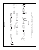
Input Parallel Speaker Jacks 4 or 8 ohms -10 dB Pad Pre Gain Tube Stage 1/2 12AX7 Tube Stage 1/2 12AX7 Power Amplifier (8) 6550s (2) 12AX7s (1) 12AT7 400 watts RMS Resonance and Presence Low Boost Low Cut Power Amp In Tube Stage 1/2 12AX7 3-Band Passive EQ LOW - MID - HIGH DDT Circuit Defeat Switch High Boost 3-Band Passive EQ LOW - MID - HIGH Clean Channel Pre Gain Low Boost High Boost Mid Shift Switch Logic Preamp Out Post Gain This flowchart illustrates signal flow within the unit.
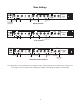
Tone Settings -10 dB PAD INPUT CRUNCH CLEAN 5 4 8 8 PRE GAIN SELECT COMBINE 400 600 800 8 MID SHIFT MID LOW 0 -10 dB PAD 8 2 PRE GAIN LOW HIGH BOOST 8 0 Classic® 400 7 8 9 1 10 0 RESONANCE DDT™DEFEAT 6 2 9 1 POST GAIN HIGH 8 2 10 ON ON 5 4 3 7 10 PRESENCE MADE IN U.S.A. HIGH BOOST LOW BOOST "OUT" "OUT" 8 0 6 3 DDT™ 9 1 10 0 MID 7 2 9 1 10 0 5 4 6 3 7 2 9 1 10 0 5 4 6 3 7 Set above 5, distortion dependent on instrument level.
E S PA Ñ O L Consulte los diagramas del panel delantero en la sección de inglés de este manual.
INPUT (Entrada) (2) Esta entrada aceptará señales de todo tipo de captadora de bajo eléctrico. CHANNEL SELECT SWITCH (Conmutador selector de canales) (3) Permite la selección del canal “clean” o "crunch" (crujido). La posición hacia dentro selecciona el canal crujido y la posición hacia fuera selecciona el canal "clean". Nota: La selección de canales también puede efectuarse mediante el conmutador de pedal remoto.
HIGH CONTROL — CRUNCH CHANNEL (Control del ecualizador de frecuencias agudas) (19) Es un control passivo de tono, que ajusta las frecuencias agudas. HIGH BOOST SWITCH — CRUNCH CHANNEL (Interruptor de refuerzo de agudas) (20) Filtro pasivo de alta frecuencia; proporciona un refuerzo de las frecuencias agudas cuando el botón está oprimido. POST GAIN — CRUNCH CHANNEL (Control de ganancia posterior al preamplificador) (21) Controla el nivel global de volumen del canal "Crunch".
AC LINE CORD SOCKET (Tomacorriente para el cable de corriente) (30) Se suministra para enchufar el cable de corriente. PARALLELED SPEAKER JACKS (Enchufes hembra para altavoces en paralelo) (31) Se proporcionan dos enchufes hembra para altavoces de 1/4 de pulgada. Estos enchufes están en paralelo. El conmutador de impedancia selecciona la impedancia total según la carga del amplificador.
FRAN ÇAI S Veuillez-vous référer au “front panel” situé dans la section en langue anglaise de ce manuel. Caractéristiques du Classic® 400 . Préampli et ampli de puissance à tubes . Huit tubes de puissance 6550 . Cinq 12AX7 et un 12AT7 . Compression brevetée DDT™ du préampli (désactivable par bouton-poussoir) . Aucun dispositif monolithique dans le chemin du signal . Activation et combinaison des canaux à distance . Boucle d’effets activable à distance . Commandes de résonance et de présence .
CHANNEL SELECT SWITCH (Commutateur de sélection des canaux) (3) Permet de sélectionner les canaux « clean » ou « crunch ». La position « in » du sélecteur correspond au canal « crunch ». La position « out » sélectionne le canal « clean ». Remarque : Il est possible de sélectionner les canaux avec la pédale de commande à distance. Pour ce faire, mettre au préalable le commutateur en position « out ».
POST GAIN SWITCH — CRUNCH CHANNEL (21) Commande le volume général du canal « Crunch ». Le réglage final de niveau doit être effectué après avoir obtentu la sonorité désirée à l’aide des autres réglages. DDT ™ INDICATOR (DEL témoin de DDT™) (22) S’allume jaune lorsque la compression DDT est en service. DDT ™ DEFEAT SWITCH (Commutateur de désactivation de la compression DDT ™) (23) La compression DDT de l’ampli de puissance est désactivée quand ce commutateur est en position « in ».
PARALLELED SPEAKER JACKS (Jacks de haut-parleurs en parallèle) (31) Deux jacks en parallèle de 6,35 mm (1/4 po.) sont fournis. Le commutateur d’impédance permet de sélectionner l’impédance totale reçue dans l’ampli. IMPEDANCE SELECTOR SWITCH (Commutateur de sélection de l’impédance) (32) Permet de sélectionner l’impédance de la charge totale reçue dans les jacks de haut-parleurs de l’ampli. Remarque : Lorsqu’il s’agit de haut-parleurs en série, l’impédance est additionnée.
DEUTSCH Siehe Diagramm der Frontplatte im englischen Teil des Handbuchs.
CHANNEL SELECT SWITCH (Kanalwahlschalter) (3) Erlaubt die auswahl des clean-oder des crunch-kanals. Die “in”-position des schalters wählt den crunchkanal, die “out”-position den clean-kanal an. Hinweis: Die Kanalwahl kann auch über den Fußschalter erfolgen. Den Wahlschalter nicht drücken, wenn eine fernbediente Umschaltung gewünscht wird. CHANNEL COMBINE SWITCH (Kanal-Kombinations-Schalter) (4) Zur Wahl eines Einzelkanals oder kombiniertem Kanalbetrib.
HIGH BOOST SWITCH — CRUNCH CHANNEL (Höhenbetonungsschalter) (20) Passiver Hochfrequenzfilter, der die hohen Frequenzen verstärkt, wenn die Taste gedrückt ist. POST GAIN SWITCH — CRUNCH CHANNEL (21) Regelt die Gesamtlautstärke des Crunch-Kanals. Eine endgültige Pegeleinstellung sollte erfolgen, wenn der gewünschte Sound erreicht Wurde. DDT™ INDICATOR (DDT™ CompressionZeiger) (22) Leuchtet auf gelb, wenn DDT-Compression stattfindet.
AC LINE CORD SOCKET (Stromanschluss) (30) Zum Anschliessen des abnehmbaren Wechselstrom-Kabels. PARALLELED SPEAKER JACKS (Parallele Lautsprecherbuchsen) (31) Es sind zwei 6,3 mm Lautsprecherbuchsen vorhanden, die parallel geschaltet sind. Mit dem Impedanzschalter wird die gesamte am Verstärker angeschlossene Impedanz gewählt. IMPEDANCE SELECTOR SWITCH (Impedanzwahlschalter) (32) Dient zur Wahl der Impedanz der gesamten Last, die an den Lautsprecherbuchsen des Verstärkers angeschlossen ist.
THIS LIMITED WARRANTY VALID ONLY WHEN PURCHASED AND REGISTERED IN THE UNITED STATES OR CANADA. ALL EXPORTED PRODUCTS ARE SUBJECT TO WARRANTY AND SERVICES TO BE SPECIFIED AND PROVIDED BY THE AUTHORIZED DISTRIBUTOR FOR EACH COUNTRY. Ces clauses de garantie ne sont vaiables qu’aux Etats-Unis et au Canada. Dans tour les autres pays, les clauses de garantie et de maintenance sont fixees par le distributeur national et assuree par lul seion la legislation envigueur.
IMPORTANT SAFETY INSTRUCTIONS WARNING: When using electric products, basic cautions should always be followed, including the following. 1. Read all safety and operating instructions before using this product. 2. All safety and operating instructions should be retained for future reference. 3. Obey all cautions in the operating instructions and on the back of the unit. 4. All operating instructions should be followed. 5. This product should not be used near water, i.e.
® Features and specifications subject to change without notice. ©1996 TM ® Peavey Electronics Corporation 711 A Street / Meridian, MS 39301 / U.S.A. / (601) 483-5365 / Fax 486-1278 #80300224 Printed in U.S.A.