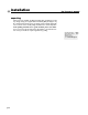
owner’s manual 8002 power amplifier Professional Power Amplifier 8002 ACL Signal Status -6 -10 -6 -10 -3 -15 -30 -80 Ch A v. 1.0 *A4400076* 4/29/98 Crest Audio Inc. 100 Eisenhower Dr., Paramus NJ 07652 USA TEL: 201.909.8700 FAX: 201.909.8744 http://www.crestaudio.
important precautions 1 Save the carton and packing materials! Should you ever need to ship the unit, use only the original factory packing. ¡ For replacement packaging,call Crest Audio’s Customer Service Department directly. 2 3 4 5 6 Do not parallel- or series-connect an amplifier output with any other amplifier output. Read all documentation before operating your equipment. Retain all documentation for future reference. Follow all instructions printed on unit chassis for proper operation.
table of contents 1 how to use this manual introduction p.3 2 installation 3 features overview 4 5 p.2 p.5 unpacking mounting cooling and ventilation powering maintenance p.11 front panel rear panel operation modes p.17 stereo parallel bridged contents connections p.21 input output 6 safety 7 service and support a specifications p.36 b block diagram p.37 c wire gauge charts p.27 tourclass protection precautions user responsibility p.
1 how to use this manual conventions terms official Crest Audio features and each indicator or control on the amplifier will appear as: terms actions specific actions or selections the user can execute will appear as: actions tasks are broken down into steps 1 2 3 warnings Procedures not to attempt. Issues or hazards to keep in mind when operating the equipment. a indicators What to look for on the equipment display. Alerts, indicators, or prompts that may appear. ® tips Prefered methods.
introduction 1 welcome Congratulations on your purchase of a new Pro II Series professional power amplifier, and thank you for your confidence in Crest Audio products.You are among the growing number of audio professionals who have made Crest Audio one of the world’s leading suppliers of professional and commercial/industrial audio systems. For your safety, please read the Important Precautions section before installing and operating the amplifier.
p.
installation / what to do with the shipping carton / proper rack-mounting technique / keeping the amplifier cooled / grounding the amplifier / required AC line voltages / routine maintenance practices 2 unpacking mounting cooling and ventilation powering maintenance p.
2 installation Pro II owner’s manual unpacking Please inspect the amplifier carefully immediately after unpacking. If you find any damage, notify your supplier/dealer immediately. Only the shipper may file a damage claim with the carrier for damage incurred during shipping. Be sure to save the carton and all packing materials for the carrier’s inspection. If the packing materials are in good condition, please save them.
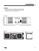
installation 2 mounting All Pro II Series amplifiers mount in standard 19-inch racks. Four front-panel mounting holes are provided on each amplifier.Rear mounting ears give additional support, and use of rear supports is highly recommended in all mobile and touring sound systems. Handles are fitted standard. 8002 shown Professional Power Amplifier 8002 ACL front height 5.
2 installation Pro II owner’s manual cooling and ventilation Pro II Series amplifiers use a twin-tunnel forced-air cooling system to maintain a low, even operating temperature. Drawn in by dual 105 CFM (cubic feet-per-minute) DC fans on the rear panel, air flows through the cooling fins of the channel heat-sinks,dissipating power transistor heat—then exhausts through the front panel slots. Heat sink temperature-sensing circuits control the “intelligent” variablespeed fans.
installation 2 powering Unless otherwise specified when ordered, Pro II amplifiers shipped to customers are configured as follows: North America 90–255 VAC @ 50–60Hz Europe 180–255 VAC @ 50–60Hz Asia 180–255 VAC @ 50–60Hz Australasia 180–255 VAC @ 50–60Hz a Always turn off and disconnect the amplifier from mains voltage before making audio connections. As an extra precaution, have the attenuators turned down during power-up.
p.
features overview / location of connectors and controls / legend of panel symbols 3 front panel rear panel p.
3 features overview Pro II owner’s manual 8002 shown 1 2 3 6 7 5 4 8 Professional Power Amplifier 8002 ACL Signal Status -6 -10 -6 -10 -3 -15 -1 -30 -80 Ch A p.
features overview 3 front panel 1 Rack Mounting Ears Two front-panel mounting holes are provided on each mounting ear. 2 Rack Handles 3 Fan Outlet Grills Pro II Series amplifiers are cooled by two, rear-mounted fans. Cool air flows over the heat sinks and exhausts through the front grills. Make sure these outlets remain clear to allow unrestricted airflow.
3 features overview Pro II owner’s manual 8002 shown 1 2 3 4 5 6 7 8 rear panel 1 Output Connectors rear panel legend input connection 2+ 1 3- + Pro II Series power amplifiers are supplied with both high-current fiveway binding posts and Speakons installed. Binding posts: one pair per channel. Speakons: one connector per channel, plus a third connector configured for bridged-mono operation.
features overview 3 rear panel 3 Female Balanced XLR Input Connectors 4 Male Balanced XLR Input Connectors These connectors accept input signals on balanced male and female XLR input plugs. Connectors for each channel are in parallel; any unused XLR connectors may be used for daisy-chaining input connections to other amplifiers. In Parallel and Bridge Mono mode a signal applied to channel A’s input connectors will appear also at channel B’s.
p.
operation modes / choosing the appropriate mode / switching between operation modes / keeping the amplifier cooled / special considerations when using bridged mode 4 stereo parallel bridged p.
4 operation modes Pro II owner’s manual mode selection The three-position, recessed Mode Select switch (located on the rear panel) configures the amplifier for Stereo, Parallel or Bridged mode. Amplifiers are factory-configured for Stereo mode. stereo In Stereo mode, both channels operate independently, with their input attenuators controlling their respective levels.Signal at Channel A’s input produces output at Channel A’s output,while signal at Channel B’s input produces output at Channel B’s output.
operation modes 4 p.
p.
connections / / proper wiring schemes for connectors: XLR speakon binding post input correct signal paths: stereo, parallel, and bridged output 5 p.
5 connnections Pro II owner’s manual inputs Use either male or female XLR connectors on the rear to supply audio signals to the inputs of your Crest Audio Pro II Series amplifier. Some other Crest Audio amplifiers are configured with pin 3 hot. a Pro II Series amplifiers are configured standard with pin 2 hot on XLR inputs. The input XLR polarity switch can configure pin 3 hot if required.
connections 5 stereo mode five-way binding post connectors Unused XLR connectors can be utilized to daisy-chain a signal source to additional amplifiers. parallel mode five-way binding post connectors bridged mono mode five-way binding post connectors Unused XLR connectors can be utilized to daisy-chain a signal source to additional amplifiers. Unused XLR connectors can be utilized to daisy-chain a signal source to additional amplifiers. p.
5 connnections Pro II owner’s manual stereo mode speakon output connectors Unused XLR connectors can be utilized to daisy-chain a signal source to additional amplifiers. parallel mode speakon output connectors Unused XLR connectors can be utilized to daisy-chain a signal source to additional amplifiers. bridged mono mode speakon output connectors Unused XLR connectors can be utilized to daisy-chain a signal source to additional amplifiers. p.
connections 5 p.
p.
safety / the owner’s role in amplifier safety / description of TourClass protection features / protecting your speakers 6 user responsibility speaker protection TourClass p.
6 safety user responsibility Your Pro II Series amplifier is very powerful and can be potentially dangerous to loudspeakers and operators alike. It is your responsibility to read important precautions (see the inside-front cover) and make sure that the amplifier is installed, wired, and operated properly as instructed in this manual. Many loudspeakers can be easily damaged or destroyed by overpowering, especially with the high power available from a bridged amplifier.
safety 6 speaker protection All loudspeakers have electrical, thermal, and physical limits which must be observed to prevent damage or failure. Cone or compression drivers can be damaged (sometimes to the point of failure) from excessive power, low frequencies applied to high frequency drivers, severely clipped waveforms, and DC voltage. All Pro II Series amplifiers automatically protect speakers from DC voltages and subsonic signals.
6 safety TourClass ® protection Every model in the Pro II Series incorporates TourClass protection features. Derived from Crest Audio’s extensive experience with the world’s largest sound rental companies, the TourClass group of circuits sets the industry standard for assured protection of internal amplifier circuits and all connected loads. ACL ACTIVE CLIP LIMITING At the amplifier’s full power limit, or clipping point, ACL will be activated. This is indicated by illumination of the ACL LED.
safety 6 DC Voltage If an amplifier channel detects DC voltage at its output terminals, the output relay will immediately open to prevent loudspeaker damage.The Status LEDs will turn red. Subsonic Frequencies Built-in high pass filtering provides subsonic frequency protection for each channel. In addition, a relay will open if excessive subsonic energy appears at the output. p.
p.
service and support / when to get support / ways to contact Crest Audio 7 support contact us p.
7 service and support Pro II owner’s manual support In the unlikely event that your amplifier develops a problem, it must be returned to an authorized distributor, service center or shipped directly to our factory. To obtain service, contact your nearest Crest Audio Service Center, Distributor, Dealer, or any of the worldwide Crest Audio offices. For those with Internet access, please visit the Crest Audio website.
service and support 7 p.
specifications a Pro II owner’s manual 8002 Stereo power 8Ω 1kHz, 0.1% THD+N 20Hz–20kHz, 0.
block diagram b p.
c wire gauge stranded cable length 2 5 meters meters 10 meters 30 p. 38 Pro II owner’s manual wire gauge power loss 8Ω load 4Ω load 2Ω load 0.3mm2 2.9% 5.6% 10.8% 0.5 1.74 3.4 6.7 0.75 1.16 2.3 4.5 1.5 0.58 1.16 2.3 2.5 0.35 0.70 1.39 4.0 0.22 0.44 0.87 0.5mm2 4.3% 8.2% 15.5% 0.75 2.9 5.6 10.8 1.5 1.45 2.9 5.6 2.5 0.87 1.74 3.4 4 0.55 1.09 2.2 6 0.37 0.73 1.45 0.5mm2 8.24% 5.5% 28% 0.75 5.6 10.8 19.9 1.5 2.9 5.6 10.8 2.5 1.74 2.
wire gauge stranded cable length 5 feet 10 feet 40 80 feet feet wire gauge c power loss 8 Ω load 4 Ω load 2 Ω load 18 AWG 0.81% 1.61% 3.2% 16 0.51 1.02 2.0 14 0.32 0.64 1.28 12 0.20 0.40 0.80 10 0.128 0.25 0.51 18 AWG 1.61% 3.2% 6.2% 16 1.02 2.0 4.0 14 0.64 1.28 2.5 12 0.40 0.80 1.60 10 0.25 0.51 1.01 18 AWG 6.2% 11.9% 22% 16 4.0 7.7 14.6 14 2.5 5.0 9.6 12 1.60 3.2 6.2 10 1.01 2.0 4.0 8 0.60 1.20 2.4 18 AWG 11.
owner’s manual 8002 power amplifier Professional Power Amplifier 8002 ACL Signal Status -6 -10 -6 -10 -3 -15 -30 -80 Ch A v. 1.0 *A4400076* 4/29/98 Crest Audio Inc. 100 Eisenhower Dr., Paramus NJ 07652 USA TEL: 201.909.8700 FAX: 201.909.8744 http://www.crestaudio.