® CS 800S Operating Guide
Intended to alert the user to the presence of uninsulated Òdangerous voltageÓ within the productÕs enclosure that may be of sufficient magnitude to constitute a risk of electric shock to persons. Intended to alert the user of the presence of important operating and maintenance (servicing) instructions in the literature accompanying the product. CAUTION: Risk of electrical shock Ñ DO NOT OPEN! CAUTION: To reduce the risk of electric shock, do not remove cover. No user serviceable parts inside.
CS® 800S POWER AMPLIFIER OWNERS MANUAL Congratulations on your purchase of the new CS® 800S stereo power amplifier. This latest version is the most advanced ever, using state-of-the-art switching power supply technology to deliver high fidelity and rock solid performance in a tworack-space unit that weighs just under 23 pounds.
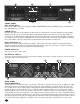
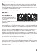
5 1 5 2 3 4 FRONT PANEL DDT™ ACTIVE LED (1) Illuminates when DDT™ Compression is taking place. With the ENABLE/DEFEAT switch in the DEFEAT position, the LED indicates when clipping distortion is occurring. POWER LED (2) Illuminates when AC power is being supplied to the amp and the associated channel is operational. Illumination is delayed slightly during the power-up cycle due to the transient suppression/thermal fault circuitry.
IEC MAINS POWER CONNECTOR (7) The CS® 800S is fitted with a universal IEC connector. Into this connector one should always insert a heavy duty #14 AWG 3 conductor line cord with a conventional AC plug with a ground pin. This line cord should be connected to an independent mains circuit capable of supporting at least 15 amps continuously or greater. This is particularly critical for sustained high power applications.
THE P1 OUTPUT MODULE (15) 15 The standard output module shipped with each amplifier is called the P1 MODULE. It offers both dual 1/4" jacks and 5-way binding post speaker outputs for each channel. For each channel, the outputs are in parallel, hence the speaker connection cables can be terminated with 1/4" phone plugs, or banana plugs or stripped wires for use in the binding post terminals.
THE S2 OUTPUT MODULE The S2 output module offers dual Speakon® Quick Connectors and a unique patching capability to wire these connectors to meet the particular application. The Speakon® is a four-wire connector with the connections labeled as 1+, 1-, 2+ and 2-. Depending upon the loudspeaker needs, these connections can be used in various ways. NOTE: Consult your loudspeaker specifications to determine the wiring configuration (mode) that will best suit your system.
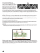
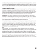
THE S2 OUTPUT MODULE REAR VIEW - BRIDGE MODE (19) 19 The following wiring allows the Speakons to be the bridge outputs with both in parallel. Such an arrangement permits two 8 ohm enclosures to be connected in parallel to the CS-S amp in Bridge Mode. In this case, the wiring is as follows: 1+ on both connectors wired to Channel A signal output; 1- on both connectors wired to Channel B signal output; 2+ and 2- on both connectors not used.
Inadequate cooling due to preheated air, a reduction of air flow caused by blockage of the amplifier's inlet/outlet ports, or severely overloading the amp may cause the amplifier's thermal sensing system to temporarily shut down that particular channel. This will be indicated by the channel power LED on the front panel ceasing to illuminate. Depending upon available cooling air, operation will be restored to that channel relatively quickly, and the power LED will then be illuminated.
÷ ESPANOL MANUAL DEL PROPIETARIO DEL AMPLIFICADOR DE POTENCIA CS® 800S Lo felicitamos por la compra del nuevo amplificador de potencia estereofónico CS® 800S. Esta versión, la más reciente y avanzada existente, utiliza la última palabra en tecnología de conmutación de estado sólido para brindar alta fidelidad y un sólido rendimiento en una unidad que ocupa dos espacios de rack y pesa menos de 10,4 kg.
• Eficaz diseño de filtro de bajo costo, con baja EMI (interferencia electromagnética) por conducción • Totalmente operacional hasta con 85 VCA de suministro de la red (voltaje nominal de 110 V) y 170 VCA (voltaje nominal de 220 V) Sin duda comprobará que nuestro CS 800S no es simplemente otro amplificador de potencia, sino el mejor amplificador que pudo haber comprado. Por favor lea cuidadosamente este manual del propietario. Le ayudará a usar más efectivamente este interesante producto.
INTERRUPTOR DE MODO DDT™ (8) Este interruptor se usa para activar (ENABLE) o anular (DEFEAT) el compresor DDT™. INTERRUPTOR DE MODO (9) Este interruptor se usa para seleccionar los modos de operación STEREO (estéreo) o BRIDGE (puente). MODULO DE ENTRADA B1 (10) El módulo de entrada estándar que se envía junto con el amplificador se denomina MODULO B1. Cada canal cuenta con entradas XLR balanceadas electrónicamente y cuasibalanceadas con enchufe hembra fonográfico.
Independientemente del tipo de conexiones a usar, la carga mínima de los altavoces en paralelo debe limitarse siempre a 2 Ω por canal o 4 Ω en el modo de puente para cualquier aplicación. En las aplicaciones de operación en forma sostenida, es preferible operar con cargas de 4 Ω por canal u 8 Ω en modo de puente, debido al hecho de que el amplificador funcionará mucho más frío con estas cargas.
otros dos se “almacenan”. Tenga a bien notar que ahora, ambos bornes rojos están conectados a la salida del Canal A y ambos bornes negros están conectados a la salida del Canal B. En consecuencia, para conectar altavoces adicionales en modo puente, se debe utilizar un par de bornes rojo y negro, en lugar de conectar cruzados ambos bornes rojos, como en la disposición por defecto.
nominal de cada canal. En este caso, la potencia nominal del amplificador CS 800S es de 600 Wef por canal con 2 Ω. La potencia nominal en el modo de puente es de 1200 Wef con 4 Ω (carga mínima). La operación en el modo de puente se logra colocando el interruptor de modo en la posición “BRIDGE” (puente), conectando la carga entre los bornes rojos de ambos canales y usando el canal A como canal de entrada. En el modo de puente, todas las funciones del canal B se anulan.
MERKMALE DES VERSTÄRKERS • Zwei Rackeinheiten hoch, weniger als 43 cm Tiefe • Gewicht unter 11 kg, Schaltnetzteil • Einsteckbare Eingangsmodule • Zwei XLR-Buchsen (symmetrisch)/Klinkenbuchsen (unsymmetrisch) mit Durchschleifausgang pro Kanal • Universelles Dreiwege-Übergangsmodul • Einsteckbare Ausgangsmodule • Zwei Klinkenbuchsen und Fünfwege-Klemmschraubenanschlüsse pro Kanal • Zwei SPEAKON® Quick Connect-Anschlüsse mit wählbaren Anschlußformen • Modularer Aufbau • Austauschbare Kanal- und Netzteilmodule
RÜCKPLATTE Unterbrecher (6) Der CS® 800S verwendet einen Unterbrecher anstelle einer Netzsicherung. Dieser Unterbrecher soll den Strom zum digitalen Netzteil begrenzen und es dadurch vor Überhitzung und möglicher Beschädigung aufgrund eines Fehlerzustands im Verstärker schützen. Der Auslösestrom wurde sorgfältig gewählt, so daß eine kontinuierliche hohe Ausgangsleistung bei gleichzeitigem Schutz des Netzteils möglich ist.
Dieser quasi-symmetrische Schaltkreis funktioniert „automatisch“ und macht sich beim normalen Betrieb nicht bemerkbar. Er kann nicht deaktiviert werden. Klinken-Durchschleifbuchse (14) Diese mit „thru“ bezeichnete Buchse befindet sich an jedem Kanal. Sie bietet eine sehr praktische Möglichkeit zum Herstellen von Steckverbindungen.
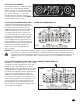
RÜCKSEITE des S2 AUSGANGSMODUL - STANDARD STEREO MODE (17) Die nachfolgende Speakon(r) Verdrahtung sieht wie folgt aus: 1+ entspricht dem Output (Ausgang) des Channel Signals und 1- der Masse des Channel Chassis. Dies ist der de facto Standard der meisten Lautsprechersysteme im unteren und mittleren Bereich. Diese Verdrahtung erlaubt den Anschluß eines Gehäuses an Kanal A und eines weiteren an Kanal B. In dieser Anwendung bleiben die Anschlüsse 2+ und 2- unbenutzt.
sich an der Rückplatte. Die Frontplatte verfügt über LED-Anzeigen für Betrieb und DDT-Aktivierung, Empfindlichkeitsregler und einen Netzschalter. Industrielle und kommerzielle Installation Für kommerzielle und andere Einsätze, wo Betrieb mit hoher Leistung über lange Zeit erforderlich ist, sollte der CS 800S in einem 19-Zoll-EIA-Rack montiert werden.
Da der Endverstärker CS 800S einen Unterbrecher als Überstromschutz einsetzt, spielt das DDT-Kompressionssystem bei längeren Auftritten eine noch wichtigere Rolle, da es Übersteuerung und Überlastung der einzelnen Kanäle verhindert. Dauerbetrieb bei Übersteuerung kann zum Auslösen des Unterbrechers führen, aber bei aktiviertem DDT-System ist dieses Problem minimal. Aus diesem Grund sollte das DDT-Kompressionssystem ständig aktiviert sein.
• Conception avec filtre économique efficace ... faibles interférences électromagnétiques par conduction • Opérationnel jusqu’à 85 VCA (US) ... 170 VCA (Export) Nous espérons qu’à vos yeux, le CS® 800S ne sera pas seulement un autre ampli, mais que vous le considérerez plutôt comme l’appareil le plus remarquable que vous ayiez jamais eu. Lisez attentivement ce manuel d’utilisation, il vous permettra de tirer le meilleur parti de votre nouvel équipement.
INTERRUPTEUR DE MODE (9) Cet interrupteur sert à sélectionner le mode de fonctionnement STEREO ou BRIDGE (pont) MODULE D’ENTREE B1 (10) Le module d’entrée standard livré avec chaque amplificateur s’appelle le MODULE B1. Sur chaque canal, il offre à la fois l’entrée électronique XLR symétrique et l’entrée casque quasi-symétrique, utilisant le nouveau connecteur « combo » de Neutrik afin de réduire l’encombrement du panneau avant.
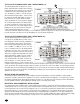
VUE ARRIERE DU MODULE DE SORTIE P1 (16) Le schéma ci-dessus illustre le câblage du MODULE P1. Remarquez que celui-ci est à l’envers. Il s’agit de la position recommandée pour reconnecter ce module ou tout autre module. Lorsque les connexions correctes des fiches à languettes de 6,3 mm (1/4 po.) sont effectuées, le module peut être pivoté vers le haut, inséré dans le panneau arrière du CS® 800S et les vis du panneau peuvent être replacées.
sont connectées à la sortie masse du canal B. Cette configuration nécessite deux cavaliers par canal soit quatre au total. Reportezvous toujours au diagramme et vérifiez vos connexions. Les deux bornes rouges sont connectées à la sortie du canal A, et les deux bornes noires sont connectées à la masse. Ainsi, chaque paire noir/rouge constitue une sortie basse fréquences et peut être utilisée pour alimenter des subwoofers supplémentaires.
Compression DDT™ Le système breveté de compression DDT™ de Peavey permet à l’ingénieur du son de maximiser les performances de l’ensemble amplificateur/haut-parleurs en empêchant l’amplificateur d’avoir une marge insuffisante (écrêtage). Ce système de compression est activé par un circuit original qui détecte les signaux susceptibles de survolter l’amplificateur, et active la compression (réduit le gain d’ampérage) lorsque l’écrêtage est imminent.
NOTES: 28
NOTES: 29
PEAVEY ELECTRONICS CORPORATION LIMITED WARRANTY Effective Date: July 1, 1998 What This Warranty Covers Your Peavey Warranty covers defects in material and workmanship in Peavey products purchased and serviced in the U.S.A. and Canada.
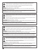
IMPORTANT SAFETY INSTRUCTIONS WARNING: When using electric products, basic cautions should always be followed, including the following: 1. Read these instructions. 2. Keep these instructions. 3. Heed all warnings. 4. Follow all instructions. 5. Do not use this apparatus near water. For example, near or in a bathtub, swimming pool, sink, wet basement, etc. 6. Clean only with a damp cloth. 7. Do not block any of the ventilation openings. Install in accordance with manufacturerÕs instructions.
SPEAKON¨ IS A REGISTERED TRADEMARK OF NEUTRIK¨ AG Peavey Electronics Corporation ¥ 711 A Street ¥ Meridian, MS 39301 (601) 483-5365Fax (601) 486-1278 ¥ www.peavey.com ©1998 80304489 Printed in U.S.A.