® CS 500A 5 0 0 Wa t t P r o f e s s i o n a l S t e r e o A m p l i f i e r Operating Guide
Intended to alert the user to the presence of uninsulated “dangerous voltage” within the product’s enclosure that may be of sufficient magnitude to constitute a risk of electric shock to persons. Intended to alert the user of the presence of important operating and maintenance (servicing) instructions in the literature accompanying the product. CAUTION: Risk of electrical shock — DO NOT OPEN! CAUTION: To reduce the risk of electric shock, do not remove cover. No user serviceable parts inside.
ENGLISH CS® 500A POWER AMPLIFIER Congratulations on your purchase of the new CS® 500A stereo power amplifier. This latest version is the most advanced ever, using state-of-the-art analog power supply technology to deliver high fidelity and rock solid performance in a tworack-space unit that’s the little brother of the famous CS® 800S.
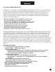
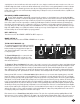
We hope you will find your new CS® 500A to be not just another power amplifier, but the most exciting power amplifier you have ever purchased. Please read over this owner’s manual carefully. It will help you to use this exciting product to its greatest capability. 5 FRONT PANEL 1 2 1 2 5 4 3 DDT™ ACTIVE LED (1) Illuminates when DDT™ Compression is taking place. With the ENABLE/DEFEAT switch in the DEFEAT position, the LED indicates when clipping distortion is occurring.
especially into a 2 ohm load, will cause the breaker to trip. If this occurs, simply reset the breaker and correct the cause of the overload. When tripped, the button on the breaker will be outward nearly 1/2" and can be reset by pushing inward. A normal reset button length is about 1/4". If this “thermal” type breaker does trip, then simply pushing the button back in will reset it after waiting a brief period of time to allow it to cool.
connected to the amp via the XLR connector and then further distributed locally via the THRU jack. Alternatively, when the 1/4" phone jack input (12) is used as the input, the THRU jack becomes a “bridged” input to it (similar to a Y-cord), again allowing this input signal to be patched to the other input jack on this amplifier or other amps in the system. IMPORTANT: The THRU jack is not intended to be “input”, and inadvertent usage as such will result in excessive loading of the input source.
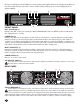
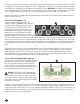
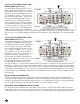
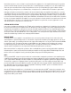
THE S2 OUTPUT MODULE (17) The S2 output module offers dual Speakon® Quick Connectors and a unique patching capability to wire these connectors to meet the particular application. The Speakon® is a four-wire connector with the connections labeled as 1+, 1-, 2+ and 2-. Depending upon the loudspeaker needs, these connections can be used in various ways. NOTE: Consult your loudspeaker specifications to determine the wiring configuration (mode) that will best suit your system.
THE S2 OUTPUT MODULE REAR VIEW 20 BRIDGE MODE Option 3 (20) The following wiring allows the Speakons to be the bridge outputs with both in parallel. Such an arrangement permits two 8 ohm enclosures to be connected in parallel to the CS®-S amp in Bridge Mode. In this case, the wiring is as follows: 1+ on both connectors wired to Channel A signal output; 1- on both connectors wired to Channel B signal output; 2+ and 2- on both connectors not used.
internal fans must have a source of air that is not preheated by other equipment. If cool, the amplifier will start up in low-speed fan operation, and will normally stay at low-speed operation unless sustained high power operating levels occur. As the amplifier heat sinks heat up, the automatic thermal sensing circuitry will increase the fan speed. Depending upon signal conditions and amp loading, the fan speed may increase to a maximum value, or it may decrease to a minimum value.
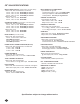
CS¨ 500A SPECIFICATIONS MUSIC POWER (IHF-202): (Typical value, 120 VAC, 60 Hz) Stereo mode, both channels driven, 20 mS burst 2 ohms, 1 kHz, 1% THD: 400 W RMS per channel 4 ohms, 1 kHz, 1% THD: 275 W RMS per channel 8 ohms, 1 kHz, 1% THD: 165 W RMS per channel Bridge mode, mono: 4 ohms, 1 kHz, 1% THD: 800 W RMS 8 ohms, 1 kHz, 1% THD: 550 W RMS CONTINUOUS POWER: (Typical value, 120 VAC, 60 Hz) Stereo mode, both channels driven 2 ohms, 1 kHz, 1% THD: 250 W RMS per channel 4 ohms, 1 kHz, 1% THD: 200 W RMS per
ESPA„OL AMPLIFICADOR DE POTENCIA CS® 500A Felicitaciones por su compra del nuevo amplificador de potencia estereofónico CS® 500A. Esta última versión es la más avanzada existente, ya que utiliza una fuente de alimentación con tecnología analógica de vanguardia que le permite proporcionar alta fidelidad y un rendimiento tan sólido como una roca en una unidad que sólo ocupa dos lugares en el bastidor: el hermano menor del antiguo CS® 800S.
• Construcción modular de canales reemplazables • Dos ventiladores de CC de velocidad variable… menor nivel de ruido • Controles de atenuador de entrada calibrado o con posiciones intermedias fijas para cada canal • LED indicadores de activación de la función DDT™ y de encendido para cada canal • Interruptor de DDT™ y del puente embutidos en el panel posterior • Conector para la línea principal aprobado por la comisión IEC • Reduce considerablemente la sobretensión transitoria que produce la línea al encen
cortacircuito y corrija el motivo de la sobrecarga. Cuando se dispara, el botón del cortacircuito sobresale casi 12 mm y usted puede restablecerlo con sólo llevarlo hacia adentro. La longitud habitual de este botón en la posición restablecida es de aproximadamente 6 mm. Si este cortacircuito tipo “térmico” se dispara, sólo es necesario oprimirlo para restablecer su función después de esperar un breve lapso para permitir que la unidad se enfríe.
Cada canal también tiene un enchufe hembra telefónico (14) identificado como “pasante”. Este enchufe hembra ofrece una capacidad para conexiones temporales muy flexible. Cuando se usan conectores de entrada XLR (11), este enchufe hembra PASANTE es la salida de los circuitos de entrada electrónicos equilibrados y, como tal, puede ser usado como “salida de línea” para conectarse con el otro enchufe hembra de entrada de este amplificador o de otros amplificadores instalados en el mismo bastidor.
MÓDULO DE SALIDA S2 (17) El módulo de salida S2 cuenta con conectores rápidos dobles Speakon® y una función única para conexiones accesorias que permite cablear estos conectores según requiera la aplicación específica. El conector Speakon® tiene cuatro cables con conexiones rotuladas 1+, 1–, 2+ y 2–. Estas conexiones pueden ser utilizadas de diversas maneras según las necesidades de los altavoces.
INSTALACIÓN Y CONEXIÓN El amplificador de potencia de la serie comercial Peavey CS® 500A fue diseñado para ofrecer durabilidad en instalaciones comerciales y alcanzar la calidad de funcionamiento que se necesita para aplicaciones en estudios de grabación tanto pequeños como profesionales. La unidad tiene una configuración estándar de montaje en bastidores, de 9 cm de alto, y se enfría mediante dos ventiladores internos de velocidad variable.
margen hasta recortar la señal (recorte). Este sistema de compresión se activa mediante un circuito exclusivo que sensa las condiciones de las señales que pueden sobrecargar el amplificador. Los circuitos reducen la ganancia del amplificador cuando el recorte de la señal es inminente. El umbral de la compresión es, por lo tanto, el recorte en sí mismo y por ello no se utiliza ningún control de umbral específico.
ESPECIFICACIONES DEL AMPLIFICADOR DE POTENCIA CS¨ 500A POTENCIA MUSICAL (IHF-202): (Valor t’pico, 120 V CA, 60 Hz) Modo estereof—nico, ambos canales excitados, sobreamplificaci—n brusca (r‡faga) de 20 mS 2 W, 1 kHz, 1% de THD: 400 Wef por canal 4 W, 1 kHz, 1% de THD: 275 Wef por canal 8 W, 1 kHz, 1% de THD: 165 Wef por canal Modo de puente, monoaural: 4 W, 1 kHz, 1% de THD: 800 Wef 8 W, 1 kHz, 1% de THD: 550 Wef POTENCIA CONTINUA: (Valor t’pico, 120 V CA, 60 Hz) Modo estereof—nico, ambos canales excitados 2
FRAN‚AIS AMPLIFICATEUR DE PUISSANCE CS® 500A Nous vous félicitons pour l’achat de cet amplificateur stéréo CS® 500A. Cette nouvelle version de notre amplificateur CS® 400X conserve toutes les performances de son prédécesseur et utilise à présent une alimentation analogique qui en fait le petit frère du CS® 800S. Cet amplificateur est capable de travailler sous 2 Ohm par canal pour une puissance de sortie impressionnante et n’occupe que 2 unités rack.
Veuillez-vous référer au <> art situé dans la section en langue anglaise de ce manual. PANNEAU AVANT LED D’ACTIVATION DDT™ (1) S’illumine lorsque la protection DDT™ se met en route. Lorsque le sélecteur ENABLE/DEFEAT est en position DEFEAT, la LED indique que l’amplificateur est en distorsion. LED D’ALIMENTATION (2) S’illumine lorsque l’amplificateur est sous tension et lorsque le canal associé est opérationnel. L’illumination est retardée à la mise en route.
Les entrée XLR femelles (11) sont connectées à un ampli-op double ultra-silencieux et possédant un taux de réjection en mode commun extrêmement élevé pour éliminer toutes interférences externes. Les entrées Jack femelles (12) au centre des connecteurs combo sont connectées à un circuit quasi-symétrique. La masse de ces connecteurs est connectée à la masse châssis au travers d’un circuit à basse impédance destiné à éliminer les boucles de masse.
MODULE DE SORTIE S2 (17) Le module de sortie S2 est équipé de deux prises Speakon(r) et permet différents types de connexions pour diverses applications. Le connecteur Speakon(r) possède quatre bornes nommées 1+, 1-, 2+ et 2-. En fonction des besoins, elles peuvent être utilisées de plusieurs manières. NOTE: Reportez-vous aux caractéristiques de vos enceintes pour déterminer la configuration (mode) idéale de votre système.
INSTALLATIONS COMMERCIALES ET PROFESSIONNELLES Pour ce genre d’installation qui exige un fonctionnement à haute puissance, les amplificateurs doivent être installés dans un rack standard de 19 pouces. Il n’est pas nécessaire d’aménager un espace entre les amplificateurs de la pile car les ventilateurs absorbent l’air extérieur par l’arrière, et le rejettent par le devant. Toutefois, une source d’air FRAIS doit être fournie à l’amplificateur s’il est monté en rack.
CS¨ 500A SPECIFICATIONS MUSIC POWER (IHF-202): (Typical value, 120 VAC, 60 Hz) Stereo mode, both channels driven, 20 mS burst 2 ohms, 1 kHz, 1% THD: 400 W RMS per channel 4 ohms, 1 kHz, 1% THD: 275 W RMS per channel 8 ohms, 1 kHz, 1% THD: 165 W RMS per channel Bridge mode, mono: 4 ohms, 1 kHz, 1% THD: 800 W RMS 8 ohms, 1 kHz, 1% THD: 550 W RMS CONTINUOUS POWER: (Typical value, 120 VAC, 60 Hz) Stereo mode, both channels driven 2 ohms, 1 kHz, 1% THD: 250 W RMS per channel 4 ohms, 1 kHz, 1% THD: 200 W RMS per
DEUTSCH CS® 500A HOCHLEISTUNGSENDSTUFE Herzlichen Glückwunsch zum Kauf der neuen CS® 500A Endstufe. Diese neue Version übertrifft alle Vorgängermodelle, sie verfügt über eine Schaltnetzteil-Technologie nach dem neuesten Stand der Technik und bietet eine hohe Reproduktionstreue und grundsolide Leistung, verpackt in nur 2 HE Rackspace.
Siehe Diagramm der Frontplatte im englischen Teil des Handbuchs. DIE FRONT DDT™ ACTIVE LED (1) Leuchtet bei Aktivierung des DDT™ Compressionssystems. Mit der Umschaltung ENABLE/DEFEAT (Rückseite) in der DEFEATPosition, zeigt die LED das clippen/verzerren des Signals an. POWER LED (2) Zeigt die Bereitschaft des Gerätes an. Wenn ein Kanal nicht einwandfrei funktioniert oder durch die Schutzschaltung abgeschaltet wird, geht die LED aus.
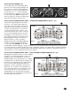
B1-Eingangsmodul (10) Das Standard-Eingangsmodul, mit dem der Verstärker geliefert wird, wird als B1-Modul bezeichnet. Es verfügt sowohl über elektronisch symmetrische XLR-Buchsen als auch quasi-symmetrische Klinkenbuchsen für jeden Kanal, wobei die neuen KomboAnschlüsse von Neutrik zur Platzeinsparung eingesetzt werden.
beiden roten Klemmschraubenanschlüsse angeschlossen. Die roten Klemmschraubenanschlüsse für Kanal A sollten dann als positiver Ausgang des Systems angesehen werden und daher mit den positiven Eingängen des Lautsprechersystems verbunden werden. Unabhängig von der Art des Anschlusses muß die minimale parallele Lautsprecherbelastung für jede Anwendung immer auf 2 Ohm pro Kanal bzw. auf 4 Ohm im Bridge-Modus begrenzt werden. Ein Betrieb bei Lasten von 4 Ohm pro Kanal bzw.
”Lager”position gebracht (2+2-). Beide roten (+) Klemm-Schraubanschlüsse sind nun auf Kanal A und beide schwarzen (-) KlemmSchraubanschlüsse sind auf Kanal B zusammengeführt. Sie müssen also, wie sonst bei Peavey üblich, NICHT die beiden roten Pole verwenden, sondern einen roten Anschluß für (+) und einen schwarzen Anschluß für (-)! DAS S2 OUTPUT MODUL RÜCKANSICHT- BIAMP MODE Option 4 (21) Diese Anschlußart ist für Biamping gedacht. Sie benötigt alle vier Pole der Speakon® Stecker.
Doppelten der Nennbelastbarkeit eines Kanals gleicht. Der CS® 500A weist eine Nennleistung von 250 W eff. pro Kanal an 2 Ohm auf. Demzufolge beträgt die Nennleistung im Überbrückungsmodus 500 W eff. an 4 Ohm (minimale Last). Der Überbrückungsmodus wird aktiviert, indem der Modusschalter auf die entsprechende Position gestellt, die Last zwischen den roten Klemmschrauben der Kanäle angeschlossen und der Kanal A als Eingangskanal verwendet wird, wodurch alle Funktionen von Kanal B deaktiviert werden.
CS¨ 500A SPECIFICATIONS MUSIC POWER (IHF-202): (Typical value, 120 VAC, 60 Hz) Stereo mode, both channels driven, 20 mS burst 2 ohms, 1 kHz, 1% THD: 400 W RMS per channel 4 ohms, 1 kHz, 1% THD: 275 W RMS per channel 8 ohms, 1 kHz, 1% THD: 165 W RMS per channel Bridge mode, mono: 4 ohms, 1 kHz, 1% THD: 800 W RMS 8 ohms, 1 kHz, 1% THD: 550 W RMS CONTINUOUS POWER: (Typical value, 120 VAC, 60 Hz) Stereo mode, both channels driven 2 ohms, 1 kHz, 1% THD: 250 W RMS per channel 4 ohms, 1 kHz, 1% THD: 200 W RMS per
NOTES: 32
NOTES: 33
IMPORTANT SAFETY INSTRUCTIONS WARNING: When using electric products, basic cautions should always be followed, including the following: 1. Read these instructions. 2. Keep these instructions. 3. Heed all warnings. 4. Follow all instructions. 5. Do not use this apparatus near water. For example, near or in a bathtub, swimming pool, sink, wet basement, etc. 6. Clean only with a damp cloth. 7. Do not block any of the ventilation openings. Install in accordance with manufacturer’s instructions.
PEAVEY ELECTRONICS CORPORATION LIMITED WARRANTY Effective Date: July 1, 1998 What This Warranty Covers Your Peavey Warranty covers defects in material and workmanship in Peavey products purchased and serviced in the U.S.A. and Canada.
SPEAKON¨ IS A REGISTERED TRADEMARK OF NEUTRIK¨ AG. Peavey Electronics Corporation ¥ 711 A Street ¥ Meridian, MS 39301 (601) 483-5365 ¥ Fax (601) 486-1278 ¥ www.peavey.com ©1999 80304543 Printed in U.S.A.