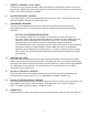
2 AUTOMIX ™ 8 Channel Automatic Mixer OPERATING GUIDE
Intended to alert the user to the presence of uninsulated Òdangerous voltageÓ within the productÕs enclosure that may be of sufficient magnitude to constitute a risk of electric shock to persons. Intended to alert the user of the presence of important operating and maintenance (servicing) instructions in the literature accompanying the product. CAUTION: Risk of electrical shock Ñ DO NOT OPEN! CAUTION: To reduce the risk of electric shock, do not remove cover. No user serviceable parts inside.
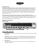
ENGLISH AUTOMIXª 2 INTRODUCTION Thank you for purchasing the Automixª 2! The Architectural Acoustics Automixª 2 is a high quality automatic mixer with eight transformer balanced mic/line inputs. Each channel provides a gain control, 48 Volt phantom power (mic inputs), low cut filter, activity/clipping LED, an Aux send control and a choice between manual or automatic operation.
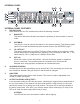
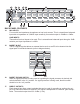
INTERNAL PANEL 8 3 9 12 10 13 11 4 5 6 7 INTERNAL PANEL FEATURES 3. DIP SWITCHES Each channel has four DIP switches that control the following functions. A. MAN/AUTO This switch determines whether the channel is operating in the automatic or manual mode. B. OFF/MBUS This switch is used to connect the channel to the system mutebus. This allows multiple inputs to be muted simultaneously under external control. See MUTEBUS, page 7. C. LO CUT/FLAT This switch selects the low cut filter.
7. PRIORITY (CHANNEL 1 and 2 ONLY) Turning the priority control clockwise allows one channel to override the others in the mix. It does this by ÒtrickingÓ the gain computing circuits into thinking this channel is louder than the others. Up to 9dB of priority is available. 8. AUX MASTER LEVEL CONTROL This control sets the level of the signal being sent to the Aux Out. This level should be set after the individual channel levels have been set. 9.
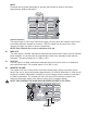
24 23 18 22 19 17 15 16 25 20 14 21 BACK PANEL FEATURES 14. MIC INPUTS For use with low impedance microphones or low level sources. This is a transformer balanced input with an impedance of 2,000½. Input sensitivity for nominal output is -56dBu to -19dBu. LINE INPUTS These allow line level inputs to be used. This is a transformer balanced input through a 30dB resistive pad. Input impedance is >20k½. 15.
MUTE Channels can be muted individually by shorting this terminal to ground. It provides approximately 45dB of attenuation. Mute with External Switch STATUS OUTPUT The status output is a DC logic output that is high (+5 Volts) when the channel is active and low (0Volts) when the channel is not active. This DC voltage can be used to key video cameras or trigger key lights on active microphones. NOTE: Each channel can source a maximum of 10 mA. 18.
21. 22. MUTEBUS The mutebus is a control port that when shorted to ground will mute all channels that are assigned to the mutebus approximately 45dB. The channels to be muted must be assigned to the mutebus using the internal switch marked OFF/MBUS. See INTERNAL PANEL FEATURES, page 4 and diagram page 7. LINK PORT To increase the number of inputs available, multiple Automixers can be linked together. Linking automixers is a very simple process.
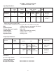
AUTOMIXª 2 SPECIFICATIONS Nominal Out = 2.21 dBu = 1 Volt Input Specifications: Function Input z (ohms) Min Input Gains Setting Microphone (150 ohms) 2k Max Gain (60dB) Line (10K ohms) >20k Min* Max Gain (30dB) Input Levels (to bal. outputs) Nominal** Bal./ Unbal. Connector Max -64dBu (0.5mV) -43dBu (5.5mV) -2dBu (615mV) Bal. Mic In (+) Mic In (-) Ground -35dBu 13.7mV -14dBu (155mV) +27dBu (17.4V) Bal.
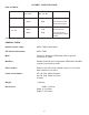
AUTOMIXª 2 SPECIFICATIONS Hum and Noise: Output Residual Noise Ref: 0 dBu Main Out S/N Ratio Ref: 2:21 dBu Test Conditions -85dBu 87dB All controls down -84dBu 86dB One channel nominal, Master level nominal -85dBu 87dB All controls down -80dBu 82dB One channel send nominal,Monitor master nominal Aux Out (Hum and noise measurements: 22 Hz to 22 kHz BW) GENERAL SPECS: Remote volume range: 0dB to 70dB of attenuation Off channel attenuation: 0dB to 70dB Mute: Channel is attenuated 45dB wh
AUTOMIXª 2 Setting up the Automixª 2 1. Wiring Inputs and Outputs: For best results, it is recommended that two-conductor shielded cable is used for all input and output connections. When making connections remember to observe proper polarity. The recommended strip length for the detachable screw terminals is 1/2". 2.
5. Setting the Overall Level: Set the master level control (external) for the desired overall output level. This mixerÕs levels are now set and the mixerÕs other features (downward expander, low cut and priorities) can be set as desired for the application. 6. Attaching the Security Panel: Attach the security plexiglass with the eight supplied screws. This will prevent any unwanted tampering with the settings.
ESPA„OL AUTOMIXª 2 INTRODUCCIîN ÁLe agradecemos haber adquirido el Automixª 2! El Architectural Acoustics Automixª 2 es un mezclador autom‡tico de alta calidad, con ocho entradas de micr—fono/l’nea equilibradas por transformador. Cada canal posee control de ganancia, alimentaci—n fantasma de 48 V (entradas de micr—fono), filtro de corte de bajos, LED indicador de actividad/recorte de se–al, control de se–al de muestra auxiliar y la opci—n de operaci—n manual o autom‡tica.
permite que varias entradas se silencien simult‡neamente mediante un control externo. Vea BUS DE SILENCIADO en la p‡gina 7. C. CORTE DE BAJOS/PLANO Este conmutador selecciona el filtro de corte de bajos. El filtro de corte de bajos provee atenuaci—n progresiva de baja frecuencia, que ayuda a minimizar los ruidos no deseados (movimiento de micr—fonos, golpes en la mesa, etc.). La atenuaci—n progresiva comienza a 100 Hz (Ð3 dB). Es un filtro de 6 dB por octava. D.
CONFIGURACIîN DEL EXPANSOR DESCENDENTE Pida a otra persona que hable frente a un micr—fono al nivel m‡s bajo que se espera utilizar. Gire lentamente el expansor descendente hacia la derecha, hasta que se atenœe el ruido ambiente de fondo entre las palabras. Tenga cuidado de no excederse. Cuanto m‡s expansor descendente se utilice, menos "natural" ser‡ el sonido del sistema.
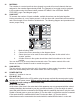
ENTRADAS DE LêNEA Permiten utilizar entradas con nivel de l’nea. Son entradas equilibradas por transformador a travŽs de un atenuador resistivo de 30 dB. La impedancia de entrada es >20 k½. 15. ENTRADA/SALIDA DE INSERCIîN Es un circuito de se–al que permite insertar un dispositivo externo, tal como un ecualizador, en el camino de la se–al de los canales individuales (consulte el diagrama m‡s abajo). Insert In/Out IN +-G OUT G-+ CEQ 280a 16.
ESTADO DE SALIDA El estado de la salida es una salida l—gica de CC que est‡ en condici—n alta (+5 V) cuando el canal est‡ activo, y baja (0 V) cuando est‡ inactivo. El voltaje de CC se puede utilizar para excitar videoc‡maras o disparar luces indicadoras en micr—fonos activos. NOTA: Cada canal puede generar un m‡ximo de 10 mA. 18. SALIDA PRINCIPAL Es una salida de 600 ½ equilibrada por transformador, que se puede utilizar con un amplificador de potencia externo.
Link Port 1. 2. 3. Prepare un cable de enlace. Conecte los mezcladores segœn el diagrama de m‡s arriba. Seleccione el mezclador a ser utilizado como maestro y coloque su conmutador de enlace en la posici—n ÒmasterÓ (maestro). 4. Todos los otros mezcladores del sistema deben tener sus conmutadores de enlace en la posici—n ÒslaveÓ (esclavo). Ahora usted cuenta con un mezclador autom‡tico de 16 canales o m‡s. Los controles maestros de la unidad elegida como "maestra" se utilizar‡n para controlar el sistema.
FRAN‚AIS AUTOMIXª 2 INTRODUCTION Nous vous fŽlicitons pour lÕachat de cet Automixª 2. LÕAutomixª 2 Architectural Acoustics est un mixeur automatique haute qualitŽ possŽdant huit entrŽes micro/ligne symŽtriques (transformateur). Chaque canal poss•de un contr™le de gain, une alimentation phantom 48 Volt (entrŽes micro), une filtre coupe-bas, une LED dÕactivitŽ/Žcr•tage, un contr™le Aux send et le choix entre une opŽration manuelle ou automatique.
C. LO CUT/FLAT Ce sŽlecteur actionne le filtre coupe-bas. Ce filtre attŽnue les frŽquences graves afin de minimiser les bruits indŽsirables (manipulation du micro, etc...). La frŽquence de coupure est fixŽe ˆ 100 Hz (-3dB) et la pente du filtre est de 6dB par octave. D. OFF/+48 Lorsque ce sŽlecteur est en position +48, une alimentation Phantom de +48 Volt est prŽsente aux bornes + et - de lÕentrŽe micro.
panneau avant sur sa position maximum, tous les canaux au niveau nominal et les amplificateurs de puissance en marche et ˆ leur niveau dÕutilisation normale. Lorsque le niveau est Žtabli en dessous du niveau de feedback, aucune manipulation en face avant nÕentra”nera de larsen. Ce rŽglage permet jusquÕˆ 25dB dÕattŽnuation du gain du syst•me. 11. NIVEAU DU NOTCH FILTER Ce rŽglage dŽtermine lÕintensitŽ de la coupure du filtre ˆ la frŽquence sŽlectionnŽe par le contr™le n¡12.
rŽcupŽrer le signal dÕun canal individuel. Ce signal est indŽpendant des manipulation de gain automatiques. Son niveau de sortie nominal est de 2.21dBu (1 Volt). MUTE Les canaux peuvent •tre mis en sourdine individuellement en mettant cette borne ˆ la masse. LÕattŽnuation est de lÕordre de 45dB. Mute with External Switch ETAT DE SORTIE Cette sortie est une sortie logique en Žtat haut (+5 Volts) lorsque le canal est actif, et en Žtat bas dans le cas contraire (0Volts).
Mute Bus Remote Volume 22. PORT LINK Pour augmenter le nombre dÕentrŽes, plusieurs Automix peuvent •tre reliŽs ensembles. Pour cela, vous avez besoin dÕun simple tourne-vis et dÕune petite longueur de c‰ble 4 conducteurs blindŽ. Suivez unes ˆ unes les Žtapes ci-dessous: Link Port 1. 2. 3. Confectionnez un c‰ble adŽquat. Reliez les mixeurs comme indiquŽ par le schŽmas ci-dessus. Choisissez le mixeur master et placez son sŽlecteur Link sur la position ÒMasterÓ. 4.
DEUTSCH AUTOMIXª 2 EINLEITUNG Vielen Dank, da§ Sie sich fŸr unseren Automixª 2 entschieden haben! Der Architectural Acoustics Automixª 2 ist ein hochqualitativer Auto-Mixer mit 8 trafogeregelten Mic/Line EingŠngen. Jeder Kanal verfŸgt Ÿber einen Gain-Regler, eine 48 Volt Phantomspeisung (MikrofoneingŠnge), Low Cut Filter, AktivitŠts-/Clip-LED, einen Aux Send Regler und der Wahlmšglichkeit zwischen der Betriebsart Manuell oder Auto.
C. LO CUT/FLAT Hiermit wird der Low Cut Filter gewŠhlt. Der Low Cut Filter bietet eine abrollende Niederfrequenz die ungewollte StšrgerŠusche zu minimalisieren hilft (Mikrofonhandling, versehentliche Tischaneckung, etc. ...). Der Rolloff beginnt bei 100 Hz (-3dB) und betrŠgt 6dB pro Oktave Filter. D. OFF/+48 In der Position ã+48Ò wird eine Phantomspeisung von +48 Volt auf die Mikrofonterminals ± gelegt.
vorsichtig nicht zu weit zu gehen. Je mehr Downward Expander Sie benutzen, um so ãunnatŸrlicherÒ klingt das System. Anhand dieser Methode erhalten Sie eine gute Ausgangsposition. Die beste Einstellmethode des Downward Expander ist jedoch wŠhrend einem eigentlichen Meeting oder Event. Auf diese Weise lŠ§t sich der Downward Expander fŸr den besten Sound einstellen. Haben Sie es mit lauten und leisen Events zu tun, dann mŸssen Sie zwischen natŸrlichem Klanginhalt und Hintergrundrauschen unterscheiden. 10.
15. INSERT IN/OUT Hierbei handelt es sich um eine Signalschleife, die es einem externen GerŠt, wie z.B. einem EQ erlaubt in den Signalpfad individueller KanŠle eingeschliffen zu werden (siehe Abb.unten). Insert In/Out IN +-G OUT G-+ CEQ 280a 16. INSERT BYPASS SCHALTER Wenn kein Signalprozessor benutzt wird, oder es nicht erforderlich ist den Signalprozessor zu umgehen, sollte sich dieser Schalter in der Position ãInÒ befinden.
18. HAUPTAUSGANG (MAIN OUT) Der Hauptausgang ist ein 600½, trafogeregelter Ausgang zur Speisung externer LeistungsverstŠrker (Power Amps). Hier wird auf dem automatisch oder manuell gemixten Output zugegriffen. Der Nominalausgang betrŠgt 2.21 dBu (1 volt). 19. AUX OUT Der Hilfsausgang ist ein 600½, trafogeregelter Ausgang, der sich als zusŠtzlicher nicht autogemixter Ausgang benutzen lŠ§t. Der Nominalausgang betrŠgt 2.21 dBu (1 volt). 20.
Link Port 1. 2. 3. Stellen Sie ein Verbindungskabel her. Verbinden Sie die Mixer gemŠ§ obiger Abbildung. Selektieren Sie den Mixer der als Master in Frage kommt und bringen seinen Link-Schalter in die ãMasterÒ Position. 4. Die Link-Schalter aller anderen Mixer im System sollten sich in der ãSlaveÒ Position befinden. Sie haben nun einen 16 (oder mehr) Kanal Auto-Mixer. Benutzen Sie fŸr die Systemsteuerung die Master Regler der gewŠhlten Master Einheit. 23.
PEAVEY ELECTRONICS CORPORATION LIMITED WARRANTY Effective Date: July 1, 1998 What This Warranty Covers Your Peavey Warranty covers defects in material and workmanship in Peavey products purchased and serviced in the U.S.A. and Canada.
IMPORTANT SAFETY INSTRUCTIONS WARNING: When using electric products, basic cautions should always be followed, including the following: 1. Read these instructions. 2. Keep these instructions. 3. Heed all warnings. 4. Follow all instructions. 5. Do not use this apparatus near water. For example, near or in a bathtub, swimming pool, sink, wet basement, etc. 6. Clean only with a damp cloth. 7. Do not block any of the ventilation openings. Install in accordance with manufacturerÕs instructions.
ARCHITECTURAL ACOUSTICS¨ Features and specifications subject to change without notice. Peavey Electronics Corporation ¥ 711 A Street ¥ Meridian ¥ MS ¥ 39301 (601) 483-5376 ¥ FAX (601) 486-1678 ¥ www.peavey.com ©1998 80304515 Printed in the U.S.A.