CD CD Power Amplifier Owner’s Manual
Intended to alert the user to the presence of uninsulated “dangerous voltage” within the product’s enclosure that may be of sufficient magnitude to constitute a risk of electric shock to persons. Intended to alert the user of the presence of important operating and maintenance (servicing) instructions in the literature accompanying the product. CAUTION: Risk of electrical shock — DO NOT OPEN! CAUTION:To reduce the risk of electric shock, do not remove cover. No user serviceable parts inside.
IMPORTANT SAFETY INSTRUCTIONS WARNING: When using electrical products, basic cautions should always be followed, including the following: 1. 2. 3. 4. 5. 6. 7. 8. 9. 10. 11. 12. 13. 14. 15. 16. 17. Read these instructions. Keep these instructions. Heed all warnings. Follow all instructions. Do not use this apparatus near water. Clean only with a dry cloth. Do not block any of the ventilation openings. Install in accordance with manufacturer’s instructions.
important precautions 1 Save the carton and packing materials! Should you ever need to ship the unit, use only the original factory packing. ¡ For replacement packaging,call Crest Audio’s Customer Service Department directly. 2 3 4 5 6 7 8 Do not parallel- or series-connect an amplifier output with any other amplifier output. Read all documentation before operating your equipment. Retain all documentation for future reference. Follow all instructions printed on unit chassis for proper operation.
table of contents to use this manual 1 how introduction p.2 p.3 2 installation unpacking p.5 mounting cooling and ventilation powering maintenance overview 3 features front panel p.9 rear panel operation modes 4 stereo p.15 contents parallel bridged 5 connections input p.17 output 6 safety tourclass protection p.21 precautions user responsibility 7 support contact us service and support p.25 registration a specifications p.27 b c block diagram p.
1 how to use this manual conventions terms official Crest Audio features and each indicator or control on the amplifier will appear as: terms actions specific actions or selections the user can execute will appear as: actions tasks are broken down into steps 1 2 3 warnings Procedures not to attempt. a Issues or hazards to keep in mind when operating the equipment. indicators What to look for on the equipment display. Alerts, indicators, or prompts that may appear. ® tips Preferred methods.
introduction 1 welcome Congratulations on your purchase of a new CD Series professional power amplifier and thank you for your confidence in Crest Audio products. You are among the growing number of audio professionals who have made Crest Audio one of the world’s leading suppliers of professional and commercial/industrial audio systems. For your safety, please read the Important Precautions section before installing and operating the amplifier.
installation 2 / what to do with the shipping carton / proper rack-mounting technique / keeping the amplifier cooled / required AC line voltages / routine maintenance practices unpacking mounting cooling and ventilation powering maintenance p.
2 installation CD owner’s manual unpacking Please inspect the amplifier carefully immediately after unpacking. If you find any damage, notify your supplier/dealer immediately. Only the shipper may file a damage claim with the carrier for damage incurred during shipping. Be sure to save the carton and all packing materials for the carrier’s inspection. For replacement packaging, call Crest Audio’s Customer Service Department directly. If the packing materials are in good condition, please save them.
installation 2 cooling and ventilation CD amplifiers use a forced air cooling system to maintain a low, even operating temperature. Air is drawn in by a DC fan on the rear panel, flows through the cooling fins and then exhausts through the front panel vent. Heat sink temperature is monitored and controls the variable speed fan. Fan speed increases only as required, keeping fan noise to a minimum. Keep this unit 8” from any combustible surface on all sides.
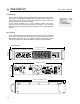
features overview 3 / location of connectors and controls / legend of panel symbols front panel rear panel p.
3 features overview CD owner’s manual CD shown 1 p.
features overview 3 front panel 1 Rack Mounting Ears Two front-panel mounting holes are provided on each mounting ear. 2 Channel Level attenuators Two input attenuators adjust level for their respective amplifier channels in stereo and in parallel modes. In Bridged Mono mode, the channel A attenuator controls overall signal level for both channels (see rear panel mode switch description). 3 Protect This Red LED indicates that the amp channel is in Protect mode.
3 features overview 1 2 CD owner’s manual 3 4 6 7 1 2 3 1 2 3 5 8 rear panel legend rear panel 1 IEC power connector Accepts a standard IEC terminated power cable 2 Breaker Resettable circuit breaker - no fuses are used. Breaker can trip due to a power surge or over-voltage condition. If it trips once, reset it. If it continues to trip, the amplifier may need servicing.
3 features overview rear panel 4 Output connections Speakers can be connected via the high current binding posts and the industry-standard Speakon (NL-4) connectors. Binding posts: One pair (Red- hot, Black- ground) per channel. Speakons - One connector for each channel.The Speakon connector for Channel A also contains contacts for Channel B out put as well (see Operation Modes).
operation modes / choosing the appropriate mode / switching between operation modes / special considerations when using bridged mode 4 stereo parallel bridged p.
4 operation modes CD owner’s manual mode selection The three-position, recessed Mode Select switch (located on the rear panel) configures the amplifier for Stereo, Parallel or Bridged mode. Amplifiers are factory-configured for Stereo mode. Shut the amp off before changing modes. stereo In Stereo mode, both channels operate independently, with their input attenuators controlling their respective levels.
connections 5 / / proper wiring schemes for connectors: speakon binding post input correct signal paths: stereo, parallel and bridged output XLR 1/4” TRS Combi Binding Posts Speakons p.
5 connections CD owner’s manual inputs CD amplifiers are configured standard with pin 2 hot on XLR inputs. female XLR TRS pinouts outputs Speakers are connected using the high-current five-way binding posts, speakon connectors, or both. stereo/parallel A and B channel Speaker + to PIN 1+ Speaker - to PIN 1A channel also has B channel + to PIN 2+ B channel - to PIN 2 Note: This is useful in bi-amp monitor situations see—operation modes p.
connections 5 stereo mode five-way binding post connectors 1 2 3 1 2 3 parallel mode five-way binding post connectors 1 2 3 1 2 3 bridged mono mode five-way binding post connectors 1 2 3 1 2 3 p.
5 connections CD owner’s manual stereo mode speakon output connectors A - + 2+ 12- 1 2 3 1+ Speaker + to PIN 1 + Speaker - to PIN 1 - 1 2 3 The Channel A Speakon has the signal from channel B present on PIN 2- and Pin 2 +. This is handy in situations where the output is driving bi-amped monitors.
safety / the owner’s role in amplifier safety / protecting your speakers / description of TourClass protection features 6 user responsibility speaker protection TourClass p.
6 safety user responsibility Your CD Series amplifier is very powerful and can be potentially dangerous to loudspeakers and operators alike. It is your responsibility to read important precautions (see the inside-front cover) and make sure that the amplifier is installed, wired, and operated properly as instructed in this manual. Many loudspeakers can be easily damaged or destroyed by overpowering, especially with the high power available from a bridged amplifier.
safety 6 TourClass protection ® Just like Crest Audio’s highly acclaimed Pro series amps, CD series amps incorporate TourClass protection features. Derived from Crest Audio’s extensive experience with the world’s largest sound rental companies, the TourClass group of circuits sets the industry standard for assured protection of internal amplifier circuits and all connected loads. ACL ACTIVE CLIP LIMITING At the amplifier’s full power limit, or clipping point, ACL will be activated.
service and support / when to get support / ways to contact Crest Audio 7 support contact us p.
7 service and support CD owner’s manual support In the unlikely event that your amplifier develops a problem, it must be returned to an authorized distributor, service center, or shipped directly to our factory. To obtain service, contact your nearest Crest Audio Service Center, Distributor, Dealer, or any of the worldwide Crest Audio offices. For those with Internet access, please visit the Crest Audio web site. contact us customer service phone 201.909.8700 USA fax 201.909.
specifications a CD Series 1kHZ, 0.
b block diagram CD owner’s manual Channel A Inputs OUTPUT STAGE A ATTENUATOR 1/4 TRS ACL, IGM, DC PROTECT, AUTORAMP Channel A Outputs 5-Way Binding Posts Neutrik Speakon THERMAL 1 3 Female 3-Pin XLR 2 A Channel B Inputs B MODE SWITCH 1/4 TRS 1 Female 3-Pin XLR X40 GAIN SWITCH - 3 2 C B A A: PARALLEL B: STEREO C: BRIDGED B ATTENUATOR 0.775V X20 VU METER OUTPUT RELAY 0.
optional handle installation c The CD amplifiers can be outfitted with optional handles.This option requires (2) CD series handles (P/N C32000010) and (4) #8-32 1/2” undercut flat head screws (P/N C38000008).You may order these from your dealer or directly from Crest Audio. p.
d wire gauge stranded cable length 2 5 wire gauge meters meters 10 meters 30 p. 30 CD owner’s manual power loss 8 Ω load 4 Ω load 2 Ω load 0.3mm2 2.9% 5.6% 10.8% 0.5 1.74 3.4 6.7 0.75 1.16 2.3 4.5 1.5 0.58 1.16 2.3 2.5 0.35 0.70 1.39 4.0 0.22 0.44 0.87 0.5mm2 4.3% 8.2% 15.5% 0.75 2.9 5.6 10.8 1.5 1.45 2.9 5.6 2.5 0.87 1.74 3.4 4 0.55 1.09 2.2 6 0.37 0.73 1.45 0.5mm2 8.24% 5.5% 28% 0.75 5.6 10.8 19.9 1.5 2.9 5.6 10.8 2.5 1.74 2.
wire gauge d stranded cable length 5 wire gauge feet 10 feet 40 80 feet feet power loss 8 Ω load 4 Ω load 2 Ω load 18 AWG 0.81% 1.61% 3.2% 16 0.51 1.02 2.0 14 0.32 0.64 1.28 12 0.20 0.40 0.80 10 0.128 0.25 0.51 18 AWG 1.61% 3.2% 6.2% 16 1.02 2.0 4.0 14 0.64 1.28 2.5 12 0.40 0.80 1.60 10 0.25 0.51 1.01 18 AWG 6.2% 11.9% 22% 16 4.0 7.7 14.6 14 2.5 5.0 9.6 12 1.60 3.2 6.2 10 1.01 2.0 4.0 8 0.60 1.20 2.4 18 AWG 11.9% 22% 37% 16 7.
http://www.crestaudio.com CD Owner's Manual Version 1.