™ PROFESSIONAL POWER AMPLIFIERS OWNER’S MANUAL
Intended to alert the user to the presence of uninsulated “dangerous voltage” within the product’s enclosure that may be of sufficient magnitude to constitute a risk of electric shock to persons. Intended to alert the user of the presence of important operating and maintenance (servicing) instructions in the literature accompanying the product. CAUTION: Risk of electrical shock — DO NOT OPEN! CAUTION: To reduce the risk of electric shock, do not remove cover. No user serviceable parts inside.
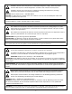
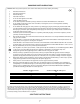
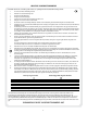
IMPORTANT SAFETY INSTRUCTIONS WARNING: When using electrical products, basic cautions should always be followed, including the following: 1. 2. 3. 4. 5. 6. 7. 8. 9. 10. 11. 12. 13. 14. 15. 16. 17. 18. Read these instructions. Keep these instructions. Heed all warnings. Follow all instructions. Do not use this apparatus near water. Clean only with a dry cloth. Do not block any of the ventilation openings. Install in accordance with manufacturer’s instructions.
WICHTIGE SICHERHEITSHINWEISE ACHTUNG: Beim Einsatz von Elektrogeräten müssen u.a. grundlegende Vorsichtsmaßnahmen befolgt werden: 1. 2. 3. 4. 5. 6. 7. 8. 9. 10. 11. 12. 13. 14. 15. 16. 17. 18. Lesen Sie sich diese Anweisungen durch. Bewahren Sie diese Anweisungen auf. Beachten Sie alle Warnungen. Befolgen Sie alle Anweisungen. Setzen Sie dieses Gerät nicht in der Nähe von Wasser ein. Reinigen Sie es nur mit einem trockenen Tuch. Blockieren Sie keine der Lüftungsöffnungen.
INSTRUCTIONS IMPORTANTES DE SECURITE ATTENTION: L’utilisation de tout appareil électrique doit être soumise aux precautions d’usage incluant: 1. 2. 3. 4. 5. 6. 7. 8. 9. 10. 11. 12. 13. 14. 15. 16. 17. 18. Lire ces instructions. Gardez ce manuel pour de futures références. Prétez attention aux messages de précautions de ce manuel. Suivez ces instructions. N’utilisez pas cette unité proche de plans d’eau. N’utilisez qu’un tissu sec pour le nettoyage de votre unité.
INSTRUCCIONES IMPORTANTES PARA SU SEGURIDAD CUIDADO: Cuando use productos electrónicos, debe tomar precauciones básicas, incluyendo las siguientes: 1. 2. 3. 4. 5. 6. 7. 8. 9. 10. 11. 12. 13. 14. 15. 16. 17. 18. Lea estas instrucciones. Guarde estas instrucciones. Haga caso de todos los consejos. Siga todas las instrucciones. No usar este aparato cerca del agua. Limpiar solamente con una tela seca. No bloquear ninguna de las salidas de ventilación.
Introduction ENGLISH CM™ Series power amplifiers feature a unique amplification architecture providing a host of user benefits including simplified operation and use in multiple applications, as well as unsurpassed sonic quality and flexible power. Easy to Use The CM 2204-AB (US model)/CM 2204-DV (European model) and CM 2208-AB (US model)/CM 2208-DV (European model) are easy to set up and operate.
Introduction Unpacking Upon unpacking, inspect the amplifier. If you find any damage, notify your supplier immediately. Only the consignee may institute a claim with the carrier for damage incurred during shipping. Be sure to save the carton and all packing materials. Should you ever need to ship the unit back to Crest Audio, one of its offices, service centers or the supplier, use only the original factory packing. If the shipping carton is unavailable, contact Crest Audio to obtain a replacement.
Operating Precautions Make sure the mains voltage is correct and is the same as that printed on the rear of the amplifier. Damage caused by connecting the amplifier to improper AC voltage is not covered by any warranty. Note: Always turn off and disconnect the amplifier from mains voltage before making audio connections. Also, as an extra precaution, turn down the attenuators before powering up.
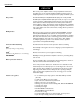
Front Panel 1 1 2 2 3 3 (1) Power Indicator The green LED indicates that AC power is supplied to the unit and the power switch is ON. (2) Signal Indicators Green LEDs indicate significant signal presence on that channel output. The Signal Indicator illuminates only when an output signal is 1 Watt or higher (at 70V). Therefore, it is possible to have an acceptably strong signal without the Signal Indicator illuminating.
Front Panel 4 4 (4) Protect Indicators 6 5 6 5 Upon powering up the unit, the Protect LEDs illuminate momentarily and then turn off one channel at a time and then remain off. During normal operation, an over-current condition can occur if the amplifier is being overdriven to the point where clipping is continuous or from a short circuit in the speaker output. The Protect LED will illuminate red when one of these conditions occurs. The internal temperature of CM™ Series amplifiers is 65º celsius.
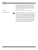
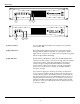
Rear Panel 7 8 + HPF 7 -6 Ch 1 HPF -6 -6 -6 + Ch 3 + Ch 2 + Inputs Ch 4 Outputs Class 2 Wiring - Gain Ch 4 Output Power per Channel 220 Watts @ 70.7 V 220 Watts @ 8 Ohms 160 Watts @ 4 Ohms Designed and manufactured in the USA by: Crest Audio, Inc. Fair Lawn, NJ USA www.crestaudio.
Rear Panel 9 9 + + HPF Ch 1 Ch 2 -6 HPF -6 -6 -6 + + Inputs Ch 3 Ch 4 Outputs Class 2 Wiring (9) Channel Inputs - Gain Ch 4 Output Power per Channel 220 Watts @ 70.7 V 220 Watts @ 8 Ohms 160 Watts @ 4 Ohms Designed and manufactured in the USA by: Crest Audio, Inc. Fair Lawn, NJ USA www.crestaudio.
Rear Panel 10 11 12 10 + + HPF Ch 1 Ch 2 -6 HPF -6 -6 -6 + + Inputs 11 Ch 3 Ch 4 Outputs Class 2 Wiring - Gain Ch 4 Output Power per Channel 220 Watts @ 70.7 V 220 Watts @ 8 Ohms 160 Watts @ 4 Ohms Designed and manufactured in the USA by: Crest Audio, Inc. Fair Lawn, NJ USA www.crestaudio.
Bridged Mode A pair of amplifier channels may be bridged together to make a single output with a power rating equal to the sum of both channel power ratings at twice the load rating of a single channel. In other words‚ bridging two amplifiers rated for 160 Watts into 4 Ohms will produce 320 Watts into 8 Ohms. In Bridged Mode‚ the channels operate at opposite polarity from each other so that one channel pushes and the other pulls equally.
Outputs in Bridged Mode The loudspeaker load is connected only to the designated positive (+) output terminals of the bridged channels. NEVER ground either side of the loudspeaker load cable when the amplifier is in Bridged Mode as both sides are “hot.” If an output patch panel is used‚ all connections must be isolated from each other and from the panel. When using the low-Z output‚ the minimum nominal load impedance in Bridged Mode is 8 Ohms; this is equivalent to driving both bridged channels at 4 Ohms.
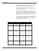
Example of a 70 Volt constant-voltage distribution system + - + - + - + - + - + - + - + - + + - + - + - + - + - + - + - + - + - - + -- + + - 20 speakers @ 10 Watts each = 200 Watts + - + + - + Ch 2 70 V Line Low Z or 70 V Line + - + Low Z or 70 V Line + - + - + - + - + Ch 1 + 70 V Line - + - Ch 3 + - Ch 4 Outputs Class 2 Wiring 17 + - 8 speakers @ 25 Watts each = 200 Watts + -
SPECIFICATIONS Specification CM™ 2208 CM 2204 160 Watts 240 Watts 230 Watts 160 Watts 245 Watts 220 Watts 4 Ohms 8 Ohms 70 Volts (24 Ohms) 150 Watts 210 Watts 170 Watts 155 Watts 240 Watts 180 Watts Minimum Load Impedance 4 Ohms 4 Ohms 320 Watts 460 Watts 320 Watts 440 Watts 8 Ohms 140 Volts 300 Watts 340 Watts 310 Watts 360 Watts Minimum Load Impedance 8 Ohms 8 Ohms -1 dB @ 1 Watt (8 Ohm Load) 5 Hz–20 kHz 5 Hz–20 kHz THD @ rated power‚ 1 kHz (70 V) <0.02% <0.
SPECIFICATIONS Specification Current Consumption CM™ 2208 CM 2204 (Multiply current by 0.5 for 230 V units) 1/3 power, 70 V output 1/8 power, 70 V output Idle 8.0 A 4.0 A <2 A 4.4 A 2.
SERVICE AND SUPPORT Support In the unlikely event that your amplifier develops a problem, it must be returned to an authorized distributor or service center or shipped directly to our factory. To obtain service, contact your nearest Crest Audio Service Center, Distributor, Dealer or any of the worldwide Crest Audio offices (available online at www.crestaudio.com). Contact Us Customer Service phone email 201.475.4600 USA custsrv@crestaudio.com Technical Support phone email 201.475.
Einführung DEUTSCH Verstärker der CM™-Serie bieten eine einzigartige Verstärkerarchitektur mit einer Vielzahl von Vorteilen für den Nutzer wie etwa der vereinfachte Betrieb und der Einsatz bei zahlreichen Anwendungen sowie eine unübertroffene Klangqualität und flexible Leistung. Einfach zu bedienen Der CM 2204-AB (US-Modell)/CM 2204-DV (Europa-Modell) und der CM 2208-AB (US-Modell)/CM 2208-DV (Europa-Modell) lassen sich ganz einfach einstellen und bedienen.
Einleitung Funktionen auf einen Blick: • Vier- oder Achtkanal-Verstärkersystem – 200 Watt RMS pro Kanal (70 Volt) • Niederohmiger (4 oder 8 Ohm) oder 70-Volt-Ausgang • Eingangsstecker: 3-Pin-Phoenix, symmetriert • Ausgangsstecker: 2-Pin-Phoenix • Umfangreiche Schutzschaltungen einschließlich ACL, IGM und AUTORAMP • Stahlgehäuse der Stärke 16 • 2 HE.
Sicherheitshinweise für den Betrieb Achten Sie darauf, dass die Netzspannung korrekt ist und mit den Angaben auf der Rückseite des Verstärkers übereinstimmt. Schäden, die aufgrund des Anschlusses des Verstärkers an eine ungeeignete Wechselspannung entstehen, werden nicht von der Garantie abgedeckt. Hinweis: Schalten Sie den Verstärker immer aus und trennen Sie ihn vom Netz, bevor Sie Audio-Geräte anschließen. Als zusätzliche Vorsichtsmaßnahme sollten Sie vor dem Einschalten die Dämpfer herunterdrehen.
Vorderseite 1 1 2 2 3 3 (1) Power-Anzeige Die grüne LED leuchtet auf, wenn das Gerät mit Wechselstrom versorgt wird und eingeschaltet ist. (2) Signalanzeigen Grüne LEDs zeigen an, dass an diesem Kanalausgang ein deutliches Signal vorhanden ist. Die Signalanzeige leuchtet nur, wenn das Ausgangssignal 1 W oder darüber beträgt (bei 70 V). Daher kann es vorkommen, dass die Signalanzeige nicht leuchtet, obwohl ein ausreichend starkes Signal vorliegt.
Vorderseite 4 4 (4) Protect-Anzeigen 6 5 6 5 Nach dem Einschalten des Geräts leuchten die Protect-LEDs kurzfristig auf, danach erlöschen sie nacheinander für den jeweiligen Kanal und bleiben ausgeschaltet. Während des normalen Betriebs kann Überlaststrom auftreten, wenn der Verstärker soweit übersteuert wird, dass das Clipping kontinuierlich wird oder ein Kurzschluss am Lautsprecherausgang vorliegt. Die Protect-LED leuchtet rot auf, wenn eine dieser Bedingungen vorliegt.
Rückseite 7 8 + HPF 7 -6 Ch 1 HPF -6 -6 -6 + Ch 3 + Ch 2 + Inputs Ch 4 Outputs Class 2 Wiring - Gain Ch 4 Output Power per Channel 220 Watts @ 70.7 V 220 Watts @ 8 Ohms 160 Watts @ 4 Ohms Designed and manufactured in the USA by: Crest Audio, Inc. Fair Lawn, NJ USA www.crestaudio.
Rückseite 9 9 + + HPF Ch 1 Ch 2 -6 HPF -6 -6 -6 + + Inputs Ch 3 Ch 4 Outputs Class 2 Wiring (9) Kanaleingänge - Gain Ch 4 Output Power per Channel 220 Watts @ 70.7 V 220 Watts @ 8 Ohms 160 Watts @ 4 Ohms Designed and manufactured in the USA by: Crest Audio, Inc. Fair Lawn, NJ USA www.crestaudio.
Rückseite 10 11 12 10 + + HPF Ch 1 Ch 2 -6 HPF -6 -6 -6 + + Inputs 11 Ch 3 Ch 4 Outputs Class 2 Wiring - Gain Ch 4 Output Power per Channel 220 Watts @ 70.7 V 220 Watts @ 8 Ohms 160 Watts @ 4 Ohms Designed and manufactured in the USA by: Crest Audio, Inc. Fair Lawn, NJ USA www.crestaudio.
Bridged-Modus Zwei Verstärkerkanäle können überbrückt werden, um einen einzigen Ausgang mit einer Nennleistung zu erhalten, die der Summe beider KanalNennleistungen bei zweifacher Nennlast eines einzelnen Kanals entspricht. So ergibt sich durch Überbrücken von zwei Verstärkern mit jeweils 160 Watt an 4 Ohm eine Leistung von 320 Watt an 8 Ohm. Im Bridged-Modus arbeiten die Kanäle mit jeweils entgegengesetzter Polarität, sodass sie im Gegentakt arbeiten.
Ausgänge im Bridged-Modus Die Lautsprecherlast wird nur an die jeweiligen positiven (+) Ausgangsklemmen der überbrückten Kanäle angeschlossen. Da beide Seiten des Lautsprecherlastkabels spannungsführend sind, darf KEINE Seite des Kabels geerdet werden, solange sich der Verstärker im BridgedModus befindet. Wird eine Ausgangsschalttafel verwendet, müssen alle Anschlüsse voneinander und von der Schalttafel isoliert werden.
Example of a 70 Volt constant-voltage distribution system + - + - + - + - + - + - + - + - + + - + - + - + - + - + - + - + - + - - + -- + + - 20 speakers @ 10 Watts each = 200 Watts + - + + - + Ch 2 70 V Line Low Z or 70 V Line + - + Low Z or 70 V Line + - + - + - + - + Ch 1 + 70 V Line - + - Ch 3 + - Ch 4 Outputs Class 2 Wiring 31 + - 8 speakers @ 25 Watts each = 200 Watts + -
Technische Daten Technische Daten CM™ 2208 CM 2204 160 Watts 240 Watts 230 Watts 160 Watts 245 Watts 220 Watts 4 Ohms 8 Ohms 70 Volts (24 Ohms) 150 Watts 210 Watts 170 Watts 155 Watts 240 Watts 180 Watts Mindestlastimpedanz 4 Ohms 4 Ohms 320 Watts 460 Watts 320 Watts 440 Watts 8 Ohms 140 Volts 300 Watts 340 Watts 310 Watts 360 Watts Mindestlastimpedanz 8 Ohms 8 Ohms -1 dB bei 1 Watt (Nennlast: 8 Ohm) 5 Hz–20 kHz 5 Hz–20 kHz Klirrfaktor bei Nennleistung‚ 1 kHz (70 V) <0.02% <0.
Technische Daten Technische Daten Leistungsaufnahme CM™ 2208 CM 2204 (230-V-Geräte: Leistungsaufnahme mit 0,5 multiplizieren) 1/3 Leistung, 70-V-Ausgang 1/8 Leistung, 70-V-Ausgang Leerlauf 8,0 A 4,0 A <2 A 4,4 A 2,3 A <1 A 724 BTU/Std. 947 BTU/Std. 473 BTU/Std 621 BTU/Std.
KUNDENDIENST UND TECHNISCHE UNTERSTÜTZUNG Technische Unterstützung Sollte bei Ihrem Verstärker tatsächlich einmal ein Problem auftreten, muss er an einen autorisierten Vertrieb, ein Servicecenter direkt an das Werk geschickt werden. Für Kundendienstleistungen wenden Sie sich bitte an das nächste CrestAudio-Servicecenter, den nächsten Vertrieb oder Händler oder eines der weltweiten Crest-Audio-Büros (s. im Internet unter www.crestaudio.com). Kontakt Kundendienst Telefon 201.475.
Introduction FRANÇAIS Les amplificateurs de puissance de la série CMTM possèdent une architecture unique permettant d’offrir à l’utilisateur une grande simplicité d’utilisation tout en étant versatiles, fiables et capables de performances impressionnantes en termes de qualité sonore et de puissance.
Introduction Revues des Caractéristiques: • • • • • • • • Amplificateur 4- ou 8-canaux de 220 Watts RMS (70V) Sorties basse-impédance (4 ou 8 Ohms) ou 70 Volt Connecteurs d’entrées symétrisés Phoenix 3-points Connecteurs de sorties Phoenix 2-points Systèmes de sécurité ACL, IGM et AUTORAMP Chassis acier (16-gauge) Format Rack standard 19” - 2U CM 2204-AB/DV: 34 lbs./35.5 lbs. CM 2208-AB/DV: 36.5 lbs./38.0 lbs.
Précautions d’Emploi Assurez-vous d’alimenter correctement votre unité – réfèrez-vous aux inscriptions sur le panneau arrière pour les besoins électriques. Tout dommages causés par une alimentation inadaptée ne sont pas couverts par la garantie. Note: Toujours mettre votre unité hors-tension avant de brancher/ débrancher tout connecteur. On pourra aussi comme précaution supplémentaire, positionnez les contrôles de gains et volumes au minimum.
Panneau Avant 1 1 2 2 3 3 (1) LED d’Alimentation Cette LED verte indique en s’illuminant que votre unité est alimentée. (2) LED de Présence de Signal Cettte LED verte vous indique la présence d’un signal à la sortie de l’étage de puissance correspondant. Elles s’illuminent pour indiquer un niveau égal ou supérieur à 1 Watt (à 70V). Il est donc possible d’obtenir un signal acceptable sans que cette LED s’illumine.
Panneau Avant 4 4 (4) Indicateurs 6 5 6 5 Au moment de la mise sous tension, cette LED s’illumine sur tous les canaux, puis s’éteint canal par canal pour indiquer leur activation respective. Passé ce délai, cette LED s’illuminera pour indiquer la mise en protection du canal correspondant, par la détection d’une surtension en entrée ou d’un court circuit entre les sortie. La température de fonctionnement interne est de 65o celsius.
Panneau Arrière 7 8 + HPF 7 -6 Ch 1 HPF -6 -6 -6 + Ch 3 + Ch 2 + Inputs Ch 4 Outputs Class 2 Wiring - Gain Ch 4 Output Power per Channel 220 Watts @ 70.7 V 220 Watts @ 8 Ohms 160 Watts @ 4 Ohms Designed and manufactured in the USA by: Crest Audio, Inc. Fair Lawn, NJ USA www.crestaudio.
Panneau Arrière 9 9 + + HPF Ch 1 Ch 2 -6 HPF -6 -6 -6 + + Inputs Ch 3 Ch 4 Outputs Class 2 Wiring (9) Entrées de Canal - Gain Ch 4 Output Power per Channel 220 Watts @ 70.7 V 220 Watts @ 8 Ohms 160 Watts @ 4 Ohms Designed and manufactured in the USA by: Crest Audio, Inc. Fair Lawn, NJ USA www.crestaudio.
Panneau Arrière 10 11 12 10 + + HPF Ch 1 Ch 2 -6 HPF -6 -6 -6 + + Inputs 11 Ch 3 Ch 4 Outputs Class 2 Wiring - Gain Ch 4 Output Power per Channel 220 Watts @ 70.7 V 220 Watts @ 8 Ohms 160 Watts @ 4 Ohms Designed and manufactured in the USA by: Crest Audio, Inc. Fair Lawn, NJ USA www.crestaudio.
Mode Pont (Bridge) Une paire d’étage de puissance peuvent être reliée pour se comporter comme un étage unique, donnant une puissance de sortie égale à la somme des puissances individuelles des étages à une impédance égale à la somme des impédances de travail des étages. Par exemple, mettre en mode Pont deux étages de puissance de 160 Watts sous 4 Ohms vous donnera un étage unique de 320 Watts sous 8 Ohms.
Sorties en mode Pont La connexion du système d’enceinte se fait par les bornes positives des canaux en mode Pont. Les bornes négatives ne doivent jamais être utilisées si l’étage d’amplification est en mode Pont. Dans le cas de l’utilisation d’un panneau de connection additionnel, toutes les connexions doivent être isolées les unes des autres et du panneau. En mode de sortie basse impédance (4 or 8 Ohms), le mode Pont vous donnera une puissance de sortie de 320 Watts à une impédance minimum de 8 Ohms.
Example of a 70 Volt constant-voltage distribution system + - + - + - + - + - + - + - + - + + - + - + - + - + - + - + - + - + - - + -- + + - 20 speakers @ 10 Watts each = 200 Watts + - + + - + Ch 2 70 V Line Low Z or 70 V Line + - + Low Z or 70 V Line + - + - + - + - + Ch 1 + 70 V Line - + - Ch 3 + - Ch 4 Outputs Class 2 Wiring 45 + - 8 speakers @ 25 Watts each = 200 Watts + -
Spécification Spécification CM™ 2208 CM 2204 160 Watts 240 Watts 230 Watts 160 Watts 245 Watts 220 Watts 4 Ohms 8 Ohms 70 Volts (24 Ohms) 150 Watts 210 Watts 170 Watts 155 Watts 240 Watts 180 Watts Impédance Minimum de sortie 4 Ohms 4 Ohms 320 Watts 460 Watts 320 Watts 440 Watts 8 Ohms 140 Volts 300 Watts 340 Watts 310 Watts 360 Watts Impédance Minimum de sortie 8 Ohms 8 Ohms -1 dB @ 1 Watt (Charge de 8 Ohm) 5 Hz–20 kHz 5 Hz–20 kHz THD @puissance mesurée‚ 1 kHz (70 V) <0.02% <0.
Spécification Spécification Consommation Electrique CM™ 2208 CM 2204 (Multipliez les valeurs par 0.5 pour les unités 230 V) 1/3 de la puissance, mode 70 V 1/8 de la puissance, mode 70 V Idle 8.0 A 4.0 A <2 A 4.4 A 2.
CONSEIL ET SUPPORT Support Dans le cas improbable où votre unité présente un problème, elle doit être retournée au distributeur, à un centre technique agréé ou à directement à l’usine de fabrication. Pour un conseil d’utilisation, contactez le centre technique agréé le plus proche, votre revendeur, le distributeur ou toute branche mondiale de Crest Audio (disponible à www.crestaudio.com). Nous contacter Service après-vente Téléphone 201.475.4600 USA e-mail custsrv@crestaudio.
Introducción ESPAÑOL Las etapas de potencia de la Serie CMTM poseen una arquitectura de amplificación única que proporciona una gran gama de posibilidades al usuario que incluyen funcionamiento simplificado y uso en múltiples aplicaciones, así como una calidad de sonido insuperable y una potencia flexible. Fácil de usar El CM 2204-AB (modelo USA)/CM 2204-DV (modelo Europeo) y el CM 2208-AB (modelo USA)/CM 2208-DV (modelo Europeo) son fáciles de operar y configurar.
Introducción Repaso de las características: • Sistemas amplificadores de potencia de 4 o 8 canales -220 vatios RMS por canal (70 Voltios) • Baja Impedancia (Low-Z) (4 u 8 Ohmios) o 70 Voltios de salida • Conectores de entrada: balanceados Phoenix de 3 pines • Conectores de salida: Phoenix de 2 pines • Amplia gama de circuitos de protección incluyendo ACL, IGM y AUTORAMP • Chasis de acero de calibre 16 • Altura de 2U de rack • CM 2204-AB/DV: 34 lbs./35.5 lbs. CM 2208-AB/DV: 36.5 lbs./38.0 lbs.
Precauciones de Operación Asegúrese de que el voltaje es correcto e igual al que va impreso en la parte trasera del amplificador. La garantía no cubre el daño causado al conectar el amplificador a un voltaje AC inapropiado. Nota: Apague y desconecte siempre el amplificador de la fuente de voltaje antes de realizar cualquier conexion de audio. Además, como precaución extra, apague los atenuadores antes de encender la unidad.
Panel Frontal 1 1 2 2 3 3 (1) Indicador de Encendido Este LED verde indica que se está suministrando corriente AC a la unidad y el interruptor de encendido está en ON. (2) Indicadores de Señal LEDs luminosos verdes indican presencia significante de señal en la salida de ese canal. El Indicador de Señal sólo se ilumina cuando una señal de salida es igual o superior a 1 vatio(a 70V). En consecuencia, es posible tener una señal aceptablemente fuerte sin que se ilumine el Indicador de Señal.
Panel Frontal 4 4 (4) Indicadores de Protección 6 5 6 5 Durante el encendido de la unidad, los LEDs de Protect se iluminan momentáneamente, luego se apagan en cada canal para permanecer apagados posteriormente. Durante una operación normal, una condición de sobre-corriente puede ocurrir si el amplificador está siendo sobrecargado hasta un punto en el que la saturación es continua o si existe un cortocircuito en la salida de altavoces.
Panel Trasero 7 8 + HPF 7 -6 Ch 1 HPF -6 -6 -6 + Ch 3 + Ch 2 + Inputs Ch 4 Outputs Class 2 Wiring - Gain Ch 4 Output Power per Channel 220 Watts @ 70.7 V 220 Watts @ 8 Ohms 160 Watts @ 4 Ohms Designed and manufactured in the USA by: Crest Audio, Inc. Fair Lawn, NJ USA www.crestaudio.
Panel Trasero 9 9 + + HPF Ch 1 Ch 2 -6 HPF -6 -6 -6 + + Inputs Ch 3 Ch 4 Outputs Class 2 Wiring (9) Entradas de Canal - Gain Ch 4 Output Power per Channel 220 Watts @ 70.7 V 220 Watts @ 8 Ohms 160 Watts @ 4 Ohms Designed and manufactured in the USA by: Crest Audio, Inc. Fair Lawn, NJ USA www.crestaudio.
Panel Trasero 10 11 12 10 + + HPF Ch 1 Ch 2 -6 HPF -6 -6 -6 + + Inputs 11 Ch 3 Ch 4 Outputs Class 2 Wiring - Gain Ch 4 Output Power per Channel 220 Watts @ 70.7 V 220 Watts @ 8 Ohms 160 Watts @ 4 Ohms Designed and manufactured in the USA by: Crest Audio, Inc. Fair Lawn, NJ USA www.crestaudio.
Modo Puente Dos canales del amplificador pueden ser puenteados conjuntamente para dar una sola salida de una potencia igual a la suma de las potencias de ambos canales al doble de carga de un solo canal. En otras palabras‚ al puentear dos amplificadores de 160 vatios a 4 Ohmios se producirán 320 vatios a 8 Ohmios. En Modo Puente‚ los canales operan con polaridad opuesta entre sí para que un canal “empuje” mientras el otro “tira” con la misma intensidad.
Salidas en Modo Puente La carga del altavoz sólo se conecta a los terminales de salida positivos (+) designados de los canales puenteados. NUNCA aterrice ninguno de los lados del cable de carga del altavoz cuando el amplificador esté en Modo Puente ya que ambos lados están “calientes.” Si se usa un panel de “patcheado”‚ todas las conexiones deben ser aisladas entre sí y con el panel.
Example of a 70 Volt constant-voltage distribution system + - + - + - + - + - + - + - + - + + - + - + - + - + - + - + - + - + - - + -- + + - 20 speakers @ 10 Watts each = 200 Watts + - + + - + Ch 2 70 V Line Low Z or 70 V Line + - + Low Z or 70 V Line + - + - + - + - + Ch 1 + 70 V Line - + - Ch 3 + - Ch 4 Outputs Class 2 Wiring 59 + - 8 speakers @ 25 Watts each = 200 Watts + -
Especificaciones Especificaciones CM™ 2208 CM 2204 160 Vatios 240 Vatios 230 Vatios 160 Vatios 245 Vatios 220 Vatios 4 Ohmios 8 Ohmios 70 Voltios (24 Ohmios) 150 Vatios 210 Vatios 170 Vatios 155 Vatios 240 Vatios 180 Vatios Mínima Carga de Impedancia 4 Ohmios 4 Ohmios 320 Vatios 460 Vatios 320 Vatios 440 Vatios 8 Ohmios 140 Voltios 300 Vatios 340 Vatios 310 Vatios 360 Vatios Mínima Carga de Impedancia 8 Ohmios 8 Ohmios -1 dB a 1 vatio (Carga de 8 Ohmios) 5 Hz–20 kHz 5 Hz–20 kHz THD a
Especificaciones Especificaciones Consumo de Corriente CM™ 2208 CM 2204 (Multiplicar la Corriente por 0.5 en las unidades de 230 V) 1/3 potencia, salida 70 V 1/8 potencia, salida 70 V A Sin operación 8.0 A 4.0 A <2 A 4.4 A 2.
SERVICIO Y SOPORTE Soporte Si su amplificador desarrollara algún problema, cosa poco probable, debe devolverlo a un distribuidor autorizado o a un servicio técnico, o mandarlo directamente a nuestra fábrica. Para obtener servicio, contacte su Servicio Técnico Crest Audio más cercano, Distribuidor, Establecimiento o cualquiera de nuestras oficinas repartidas por el mundo (disponible online en www.crestaudio.com). Contáctenos Atención al Cliente teléfono 201.475.4600 USA email custsrv@crestaudio.
CREST AUDIO LIMITED WARRANTY Effective Date: November 1, 2000 What This Warranty Covers Your Crest Audio Warranty covers defects in material and workmanship in Crest Audio products purchased and serviced in the U.S.A.
Features and specifications subject to change without notice. Crest Audio Inc. • 16-00 Pollitt Drive • Fair Lawn, NJ 07410 USA TEL: 201.475.4600 • FAX: 201.909.8744 • www.crestaudio.