CAB™ 16 Series CobraNet™ Audio Bridge CAB 16i CAB 16o CAB 16d User Manual
Intended to alert the user to the presence of uninsulated “dangerous voltage” within the product’s enclosure that may be of sufficient magnitude to constitute a risk of electric shock to persons. Intended to alert the user of the presence of important operating and maintenance (servicing) instructions in the literature accompanying the product. CAUTION: Risk of electrical shock — DO NOT OPEN! CAUTION: To reduce the risk of electric shock, do not remove cover. No user serviceable parts inside.
GENERAL CAUTIONS AND WARNINGS! To prevent electrical shock or potential fire hazards, do not expose the CAB 16 to moisture or rain. Before using this product, read the user manuals for further warnings and cautions. The following cautions should be carefully observed when installing, wiring or using this product: DO NOT use any other power supply or cable other than the one provided with this unit. DO NOT remove the top cover of the unit. There are no user serviceable parts inside.
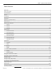
CAB™ 16 Series User Manual Table of Contents Thank You! 7 What’s In The Box? 7 Covered Products 7 Features 8 Assumptions 8 Installation 9 Hardware vs.
Table Of Contents Illustrations The CAB™ components and their relationships (Figure 1) ™ 10 The CobraNet audio transport devices and their control panels (Figure 2) 10 Recommended Test View Configuration (Figure 3) 11 Typical Network Connections (Figure 4) 22 Direct Connection Example (Figure 5) 22 Analog and Digital Audio Connections (Figure 6) 23 RS-485 Serial Data Connections (Figure 7) 23 S/PDIF resistor network configurations (Figure 8) 25 Standard “normal” CAT 5 cable (Figure 9) 26
CAB™ 16 Series User Manual CAUTION! The CAB 16 Series products are Ethernet (CobraNet™) network products designed to operate on a network backbone or infrastructure. The design, implementation and maintenance of this infrastructure is critical to the operation and performance of the CAB 16 Series products. Peavey Electronics does not support nor service network cabling, hubs, switches, patch bays, wall plates, connector panels or any other type of network interconnect device.
Welcome Thank You! Thank you for purchasing the CAB™ 16 Series CobraNet™ Audio Bridge. This product is designed to provide years of trouble-free operation, and high quality audio performance. We sincerely hope that you enjoy your new CAB 16 Series product, and will find other products in the Peavey Architectural Acoustics product line to supplement your system.
CAB™ 16 Series User Manual Features - CobraNet™ ethernet audio transport - Single rack space package - Forced air cooling - Front panel analog audio metering - Front panel network status monitoring - 24 bit D/A and A/D converters - Discreet analog design - Digital control of analog functions - 16 line level inputs (16i only) - 16 line level outputs (16o only) - 8 AES3 or S/PDIF digital audio inputs and outputs (16d only) - Full analog gain stage w/digital control (except 16d) - User defined network hardwa
Installation Installation The CAB™ 16 Series product is designed to mount in a standard EIA electronic equipment rack. Because the CAB 16 includes forced air cooling, adding rack mounted vent panels is not required for most installations. However, it is recommended that common sense be applied to large installations where multiple units are mounted in a single rack. It is generally accepted that a ratio of 2:1 is a good rule of thumb that usually provides adequate performance.
CAB™ 16 Series User Manual Hardware vs. Software Devices The CAB 16 Series of products is an integration of physical hardware and software. Within CobraNet™, there are even further integrations, that being the network itself, and the actual piece of equipment, in this case, the CAB 16. In software, the equipment is represented by a “Device” within the MediaMatrix MWare application. The CobraNet network is represented by a traditional MediaMatrix wiring block with inputs and outputs.
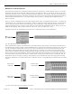
Hardware & Software The Test View In order to properly use this manual, it is recommended that a basic MediaMatrix view file be configured. This view file should have a minimum number of components and should include one each of the CAB™ 16i and CAB 16o, or, it should match exactly your specific system hardware. The following figure is a good example of such a “test” file. CobraNet Status Tool CobraNet transport device Audio from the “outside” enters the MediaMatrix system here. The yellow CAB device...
CAB™ 16 Series User Manual CAB 16i Software Device Features LINK LED This LED will turn ON when a valid connection has been established between the CAB 16 and the network switch. This function is duplicated on the front panel of the CAB 16i. ID The four digit number is the user-defined Hardware Base Address. The range is hex, between 0000 and FFFF. The LED will turn ON when a valid number is entered. Each CAB 16 on the network must have a unique ID.
Software Features CAB 16o Software Device Features LINK LED This LED will turn ON when a valid connection has been established between the CAB™ 16 and the network switch. This function is duplicated on the front panel of the CAB 16o. ID The four digit number is the user-defined Hardware Base Address. The range is hex, between 0000 and FFFF. The LED will turn ON when a valid number is entered. Each CAB 16 on the network must have a unique ID.
CAB™ 16 Series User Manual CAB 16d Software Device Features LINK LED This LED will turn ON when a valid connection has been established between the CAB 16 and the network switch. This function is duplicated on the front panel. ID The four digit number is the user-defined Hardware Base Address. The range is hex, between 0000 and FFFF. The LED will turn ON when a valid number is entered. Each CAB 16 on the network must have a unique ID.
Software Features CAB 16d Software Device Features (Input & Output Status Panels) ERROR Indicates an error has been detected on the incoming audio data stream. There is a single LED for each digital channel (2 audio channels each). SAMPLE RATE CONVERTER DISABLE Disables the on-board sample rate converters. The audio source must be locked to the CobraNet network for audio to be valid and lock. FORMAT Indicates if digital source consumer or professional grade product. Applies to each digital channel.
CAB™ 16 Series User Manual CAB 16i Front Panel Features 1 1 2 3 4 5 6 7 8 9 10 11 1. AUDIO METERS Peak reading LED ladder displays indicating audio input level in the analog domain. Signal level is displayed after the adjustable gain stage and before the A/D converters. 2. HARDWARE BASE ADDRESS SWITCHES 4-position rotary switches for setting the hardware base address. Shown with tamperproof cover removed. 3.
Panel Features CAB 16i Rear Panel Features (shown without the Euro connectors attached) 1 2 3 4 5 6 7 7 1. IEC POWER CABLE RECEPTACLE The included removable IEC power cable connects here. Use only the supplied cable. 2. POWER SWITCH Applies mains AC power to the CAB™ 16. 3. LINK OUT CONNECTOR BNC connector to transmit link data to other CAB units or third party synchronization products. 4.
CAB™ 16 Series User Manual CAB 16o Front Panel Features 1 1 2 3 4 5 6 7 8 9 10 11 1. AUDIO METERS Peak reading LED ladder displays indicating audio input level in the analog domain. Signal level is displayed after the adjustable gain stage and before the A/D converters. 2. HARDWARE BASE ADDRESS SWITCHES 4-position rotary switches for setting the hardware base address. Shown with tamperproof cover removed. 3.
Panel Features CAB 16o Rear Panel Features (shown without the Euro connectors attached) 1 2 3 4 5 6 7 7 1. IEC POWER CABLE RECEPTACLE The included removable IEC power cable connects here. Use only the supplied cable. 2. POWER SWITCH Applies mains AC power to the CAB™ 16. 3. LINK OUT CONNECTOR BNC connector to transmit link data to other CAB units or third party synchronization products. 4.
CAB™ 16 Series User Manual CAB 16d Front Panel Features 1 2 2 3 4 5 6 7 8 9 10 11 12 1. METER SELECT This meter toggles in the function of the front panel audio meters between input and output. The corresponding LED indicates the active meter function. 2. AUDIO METERS Peak reading, switchable LED ladder displays indicating audio level in the digital domain.
Panel Features CAB 16d Rear Panel Features (shown without the Euro connectors attached) 1 2 3 4 5 6 7 8 1. IEC POWER CABLE RECEPTACLE The included removable IEC power cable connects here. Use only the supplied cable. 2. POWER SWITCH Applies mains AC power to the CAB™ 16. 3. LINK OUT CONNECTOR BNC connector to transmit link data to other CAB units or third party synchronization products. 4.
CAB™ 16 Series User Manual Basic CobraNet Network Connections The CAB 16 Series products feature 4 different connection types. (Refer to the Rear Panel Details.) First in priority is the CobraNet™ network port. This RJ-45 connector is designed to connect with standard, off-the-shelf Category 5 (CAT 5) cable for use with standard Ethernet network switches. This cabling interconnect is commonly referred to as the wiring “backbone”. This backbone must be properly designed for each system.
Audio & RS-485 Connections Audio Connections The second connection is audio. Each audio connection on the CAB™ 16i and 16o is a single three-wire, balanced analog circuit. The connections on both of these units is identical, except one is an input, the other an output. The method is the same. For the CAB 16d however, the method is slightly different. Each three wire connection on the 16d is a balanced, two-channel digital (AES3 or S/PDIF, see p. 24-25) connection.
CAB™ 16 Series User Manual Using S/PDIF with the CAB 16d The CAB 16d has been designed for use with AES3 (AES/EBU) and S/PDIF (Sony/Philips Digital Interface Format) digital audio signals. The CAB 16d is shipped from the factory to accommodate AES3 digital audio right out of the box. You can connect AES sources directly to the CAB 16d’s input and output terminals without any regard to additional interface boxes or converters.
S/PDIF Connections When making these interface connections, it is important to install the resistors at the CAB™ 16d’s output terminal, using the removable Euro connector. The design of this connector, supplied with the CAB 16d, will provide a solid mechanical mount for the resistors. The wiring from the consumer RCA coax cable should be soldered to the other side of the resistor network. All interconnecting joints should be soldered as well. All resistors should be 1% or 5% tolerance, 5 W, typical.
CAB™ 16 Series User Manual CAT 5 cable is your friend.... Well, you’ve been in the audio business for a while now....you know all about audio connections, balanced cables, multi-pairs, SJO, TRS this and XLR that....you can dress off a wiring harness like nobody’s business....then, the industry throws “CAT 5” at you....
CAT 5 Cables Remember, for ethernet, the BLUE and BROWN pairs are not used. The ORANGE pair is transmit (TX), and the GREEN pair is receive (RX). There is a positive and negative conductor for each pair, indicated by the color code. Notice on the chart that the order of the wire pairs does not follow the connector pins, as mentioned earlier. Don’t let that confuse you. The first wire of a given pair is always the white wire with a colored stripe and is the positive conductor.
CAB™ 16 Series User Manual Link Connections All CAB Series products feature built-in “Buddy Link” functionality for creating backup I/O configurations in mission critical systems. The term “Buddy Link” extends to multiple dimensions within MediaMatrix, but in this context, we are concerned only with how the built-in Buddy Link works with the CAB 16 Series products.
Link Connections Network Connection Audio Output CAB 16o Primary CAB 16o Secondary or “Slave” Fig. 14, CAB 16o Link Connection Example Using the Link feature with the CAB™ 16d is basically the same as the other units, but there are several issues that must be considered when configuring the digital audio connections. It is not possible to “bus” or “Y” digital signals.
CAB™ 16 Series User Manual Setting the Hardware Base Address Once you have a valid physical connection to the network port, you now must configure the port on both ends of the network media to establish communications between the MediaMatrix software and the CAB 16. This is a critical configuration since you will not be able to pass audio or enable communications without it. Please keep in mind that there are two separate settings for successful communications on the CobraNet™ network.
Configuration Setting the Audio Bundle Now that you have established communications between the MediaMatrix software and the CAB™ 16 hardware, you will need to prepare the network to pass audio. CobraNet™ is a powerful protocol that allows you to pass up to 64 channels (32 in by 32 out) of digital audio per MediaMatrix MM-DSP-cn Digital Audio Processing card to a practically unlimited number of CAB 8 and CAB 16 Series products. The first order of business is to plan your system out.
CAB™ 16 Series User Manual Testing, Testing..... At this point, it is a good idea to see if everything is working. The example below is a good way to test your system and see how everything relates. Hook up some tunes, an amp and a speaker and see if you hear anything. The audio should be clean and clear. Listen for dropouts, distortion and other undesirable noises. If you hear any of this, especially dropouts, you've got a problem. Also, take note of the action of the front panel status LEDs.
Testing The premise here is to get audio to pass from one point to another. Audio input, the tunes, are fed via the CAB™ 16i. A Hardware Base Address of “0c92” is assigned to the 16i and entered on the front panel of the unit, and its corresponding “Taxi” device inside the software. The audio from the 16i is sent via CobraNet™ Audio Bundle 13 to the MediaMatrix MainFrame’s MM-DSP-cn DPU Card via a standard 100BaseT Ethernet Switch.
CAB™ 16 Series User Manual Testing, Testing.....digital style! When using the CAB 16d, a few additional considerations must be considered. The setup is basically the same, with the addition of the digital audio device within the CAB 16d’s Taxi device. In this example, we are showing audio sourced from digital sources, a CD player and DAT recorder, both with AES or S/PDIF inputs and outputs. The audio signal is in the digital domain throughout the signal flow.
Testing Hardware Base Address assigned to “221f”. “The Output Side” “Record Tunes” AES3 or S/PDIF Digital Audio Input CAB™ Audio Bundle set to “286” at the Taxi AND the CobraNet™ input block CAT5 Cable (typ.
CAB™ 16 Series User Manual Technical Support Peavey has an extensive Technical Services Group that provides tech support, repair and implementation services. If you require assistance with your new CAB 16, you can get help from several sources. There are many technical documents, white papers and application notes on our website and Peak Audio’s website. (See the Additional Resources section on the next page for details.
Resources Additional Resources The use of the CAB™ 16 Series products, as well as MediaMatrix and networking technology require a thorough understanding of several advanced topics. It is highly recommended that the designer acquire an understanding of these topics so that the process of systems work is efficient and cost-effective. There are several excellent sources for obtaining information regarding these topics.
CAB™ 16 Series User Manual Specifications MECHANICAL Dimensions (H x W x D) 19" W x 12-7/8" D x 1-3/4" H (48.26 x 32.70 x 4.44 cm) Weight 9.5 lbs. (4.3 kg) Mounting Single EIA Space Rack Mount Connections Removable “Euro” Connectors for each single channel of audio inputs and RS-485 bus. RJ-45 for CobraNet™ interface, BNC for link. IEC receptacle for AC power.
Specifications CAB™ 16d PERFORMANCE SPECIFICATIONS AES/EBU Input/Output Impedance: 102 Ohms Nominal, Transformer balanced Maximum Signal Attenuation for AES/EBU input: -20 dB Sample Rate Conversion Range: 32 kHz — 96 kHz Sample rate convertor locks to any sample rate (within conversion range) presented at the AES/EBU inputs Maximum Signal Rise/Fall time for AES/EBU input: 30 nS CobraNet System Latency: 5.33 ms each direction AES/EBU Output Voltage: 5 Vp-p 110 Ohm load Conversion Delay (Inputs): .
CAB™ 16 Series User Manual Architectural Acoustics® PEAVEY ELECTRONICS CORPORATION LIMITED WARRANTY Effective Date: July 1, 1998 What This Warranty Covers Your Peavey Warranty covers defects in material and workmanship in Peavey products purchased and serviced in the U.S.A. and Canada.
Features and Specifications subject to change without notice. A product of Peavey Electronics Corporation 711 A Street / Meridian, MS 39301 / USA / (601) 483-5376 / FAX (601) 486-1678 http://aa.peavey.