A A Intended to alert the user to the presence of uninsulated “dangerous voltage” within the product’s enclosure that may be of sufficient magnitude to constitute a risk of electric shock to persons. Intended to alert the user of the presence of important operating and maintenance (servicing) instructions in the literature accompanying the product. CAUTION: Risk of electrical shock - DO NOT OPEN! CAUTION: To reduce the risk of electric shock, do not remove cover. No user serviceable parts inside.
CS@ 3000G Features l 19” rack-mountable design requiring three-rack spaces l Automatic two-speed dual fan cooling system l Separate power transformers/circuit breakers for each channel l Independent channel thermal/fault protection l DDT’” activation LED and power LED, each channel l Calibrated/detented input attenuator controls, each channel l Two recessed, balanced input transformer sockets for PL-2s l Single XLR and dual phone plug inputs, each channel l XLR input can be transformer bala
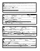
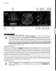
Front Panel: FRONT PANEL FEATURES CHANNELS A 81 B INPUT SENSITIVITY (1) The maximum input gain (minimum sensitivity rating) is achieved at the full clockwise setting, which yields the maximum mixer/system headroom. A setting of less than full clockwise will yield lower system noise at the expense of mixer/system headroom. Calibration indicates sensitivity in dBV necessary to attain the full available rated output power.
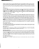
Back Panel: BACK PANEL FEATURES MAINS POWER SOURCE (6) 120 V products only A The CS 3000G is fitted with a single heavy-duty #lO AWG 3-conductor line cord and a 30 amp T/P AC plug with a large ground pin. It should be connected to an independent mains circuit capable of supporting at least 30 amps continuously or greater. This is particularly critical for sustained high power operation.
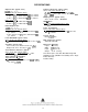
Regardless of what connections are used, the typical parallel speaker load should always be limited to 2 ohms per channel or 4 ohms Bridge mode for any application. Operation at loads of 4 ohms per channel or 8 ohms Bridge mode is more desirable for sustained operation applications due to the fact that the amplifier will run much cooler at this load.
INSTALLATION AND CONNECTION The Peavey CS 3000G commercial series power amplifier is designed for durability in commercial installations and the quality of performance required in studio and home applications. The unit is a standard rack-mount configuration, 3-l/2” high and is cooled by automatic two-speed internal fans. All of the input and output connections are on the back panel.
SPECIFICATIONS Output Power: (typical value) Frequency Response: (typical value) (@ 720 V A C , 6 0 H z ) Stereo mode. both channels driven +0,-l dB, 1 W RMS, 4 ohms: 10 Hz to 40 kHz +O, -0.
1 ‘l lnOZ-ld .
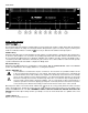
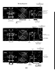
Wiring Diagrams I TO Speakers I FULL RANGE STEREO from Mln?, 10 NOTE.
Consulte 10s diagramas de1 panel delantero en la seccih de inglb de este manual. Caracteristicas de1 CS@ 3000G l Disefiado para montarse en tres espacios de bastidor de 48.
La unidad esta atractivamente empacada en una robusta configuration para montar en bastidor que requiere de solo tres espacios. Naturalmente, tiene 10s circuitos de compresion DDT patentados por Peavey y un tablero trasero muy flexible. El disefio usa doble ventilador de dos velocidades para proporcionar todo el enfriamiento necesario para las condiciones de calentamiento de la carga de 2 ohms.
Panel Trasero: FUNCIONES DEL PANEL TRASERO AC LINE CORD SOCKET (Tomacorriente para el cable de corriente) (6) A Se suministra para enchufar el cable de corriente. GROUND LIFT SWITCH (Interruptor levantamiento de tierra) (7) Este interruptor se usa para desconectar la <
LOW-Z INPUT (Entrada de baja impedancia) (9) Se proporciona un enchufe de entrada XLR hembra de tres varillas conventional y puede usarse coma el canal de entrada. Cuando no se usa el transformador de balance de linea (PL-2), esta entrada XLR se convierte en cuasibalanceada, con la varilla N”3 coma entrada positiva (conectada a la punta del enchufe para clavija de bayoneta de 6.35 mm de arriba), la varilla N”2 coma entrada negativa (conectada a la mangaflotante del enchufe para clavija de bayoneta de 6.
INSTALACdN INDUSTRIAL Y COMERCIAL Para instalaciones comerciales o de otras en las que se requiera un funcionamiento sostenido de alta potencia, el CS 3000G debe instalarse en un bastidor estandar de 48.26 cm. No se requiere dejar un espacio entre cada amplificador de la pila, ya que el ventilador absorbe aire de la parte trasera y expele el aire caliente por el frente. Sin embargo, debe proporcionarse a cada amplificador una fuente de aire ((FRESCO)).
Veuillez-vous refkrer au << front panel >> art situ6 dans la section en langue anglaise de ce manuel. Caracthistiques du CS@ 3000G l Montage en baie de 46,36 cm (19 PO.
CARACT~RISTIQUES DU PANNEAU AVANT CANAUX A ET 6 INPUT SENSITIVITY (Bouton de reglage de sensibilite de I’entrke) (1) Un gain d’entree maximum (taux de sensibilite minimum) est obtenu en tournant ce bouton a fond dans le sens des aiguilles d’une montre, ce qui produit une marge maximale pour le melangeurkysteme. Si le bouton n’est pas tourne a fond dans le sens horaire, le systeme emet moins de bruit, mais la marge reservee au melangeur/systeme s’en trouve reduite.
Panneau Arrkre : CARACTERISTIQUES DU PANNEAU ARRIlkRE AC LINE CORD SOCKET (Prise pour cdble d’alimentation) (6) A Prise de branchement du cordon d’alimentation CA detachable. GROUND LIFT SWITCH (Commutateur de separation de terre) (7) Ce commutateur set-t a deconnecter la << terre signal )) de I’amplificateur (a I’entree et a la sortie) de la
LOW-Z INPUT (EntrBe Low-Z) (9) Un jack d’entree XLR femelle ordinaire a trois broches est fourni et peut servir d’entree de canal. Lorsque le transformateur d’equilibrage des circuits (PL-2) n’est pas utilise, cette entree XLR devient quasi equilibree : la broche No. 3 sert d’entree positive (assurant la connexion avec I’extremite des jacks de 6,35 mm (l/4 PO.) ci-dessus), la broche No. 2 d’entree negative (assurant la connexion avec le manchon flottant des jacks de 6,35 mm (l/4 PO.
INSTALLATION ET CONNEXION L’amplificateur de la serie CS 3000G est concu pourfournir les performances et la qualite de son exigees pour une utilisation personnelle ou de studio. II est suffisamment resistant pour une installation a des fins commerciales. Son montage est une configuration en baie standard, il mesure 88,9 mm (3-l/2 PO.) de hauteur et il est refroidi par des ventilateurs internes automatiques a deux vitesses. Toutes les connexions d’entree et de sortie se trouvent sur le panneau arriere.
Siehe Diagramm der Frontplatte im englischen Teil des Handbuchs.
BESCHREIBUNG DER FRONTPLATTE KANAL A UND B INPUT SENSITIVITY (Eingangsempfindlichkeit) (1) Die maximale Eingangsverstarkung (minimale Empfindlichkeit) wird bei Drehung ganz nach rechts erzeugt, wo der groBte Mixer-/System-Headroom verfugbar ist. Eine geringere Einstellung ergibt weniger Systemgerausche auf Kosten des Mixer-/System-Headrooms. Die Kalibrierung gibt die Empfindlichkeit in dBV an, die erforderlich ist, urn die voile verfugbare Nennausgangsleistung zu erzielen.
Riickplatte: 0 6 0 7 BESCHREIBUNG DER RiiCKPLATTE AC LINE CORD SOCKET (Stromanschluss) (6) Zum Anschliessen des abnehmbaren Wechselstrom-Kabels. * GROUND LIFT SWITCH (Erdabhebungsschalter) (7) Dieser Schalter dient zum Abheben der ,,Signalerdung“ (Ein- und Ausgang) des CS 3000G von seiner ,,Chassiserdung“. Die Chassiserdung ist das Chassis selbst, das ijber die Befestigungsschrauben mit dem Rack und uber die Schutzkontakte des Netzkabels elektrisch geerdet ist.
LOW-Z INPUT (Niederohmiger eingang) (9) Eine konventionelle 3polige XLR-Buchse dient als Kanaleingang. Wenn der Ausgleichstransformator (PL-2) nicht verwendet wird, ist dieser XLR-Eingang quasisymmetrisch mit Stift Nr. 3 als positiver Eingang (verbunden mit der Spitze der Klinkeneingangsbuchse) und Stift Nr. 2 als negativer Eingang (verbunden mit der Muffe der Klinkeneingangsbuchse), wahrend Stift Nr. 1 zur internen Erde des Leistungsverstarkers fuhrt.
INDUSTRIELLER UND KOMMERZIELLER EINSATZ Fur kommerzielle und andere Einsatze, wo ein Betrieb mit hoher Leistung ijber eine lange Zeit erforderlich ist, sollte der CS 3000G in einem 19-Zoll-Standardrack montiert werden. Es ist nicht erforderlich, zwischen den einzelnen Verstarkern Freiraume zu lassen, da das Geblase von der Rtickseite Luft ansaugt und die warme Luft an der Vorderseite abgibt. Bei Rack-Montage muf3 jedoch fur die ausreichende Zufuhr von KUHLER Luft gesorgt werden.
THIS LIMITED WARRANTY VALID ONLY WHEN PURCHASED AND REGISTERED IN THE UNITED STATES OR CANADA. ALL EXPORTED PRODUCTS ARE SUBJECT TO WARRANTY AND SERVICES TO BE SPECIFIED AND PROVIDED BY THE AUTHORIZED DISTRIBUTOR FOR EACH COUNTRY. Ces clauses de garantie ne sont vaiables qu’aux Etats-Unis et au Canada. Dans tour les autres pays, les clauses de garantie et de maintenance sont fixees par le distributeur national et assuree par lul seion la legislation envigueur.
IMPORTANT SAFETY INSTRUCTIONS WARNING: When using electric products, basic cautions should always be followed, including the following. 1. Read all safety and operating instructions before using this product. 2. All safety and operating instructions should be retained for future reference. 3. Obey all cautions in the operating instructions and on the back of the unit. 4. All operating instructions should be followed. 5. This product should not be used near water, i.e.
Features and specifications subject to change without notice. 01996 Peavey Electronics Corporation 711 A Street / Meridian, MS 39301 / U.S.A. / (601) 483-5365 / Fax 486-1278 Printed in U.S.A.