CS®800H Operations Manual power amplifier For more information on other great Peavey products, go to your local Peavey dealer or online at www.peavey.
Intended to alert the user to the presence of uninsulated “dangerous voltage” within the product’s enclosure that may be of sufficient magnitude to constitute a risk of electric shock to persons. Intended to alert the user of the presence of important operating and maintenance (servicing) instructions in the literature accompanying the product. CAUTION: Risk of electrical shock — DO NOT OPEN! CAUTION: To reduce the risk of electric shock, do not remove cover. No user serviceable parts inside.
IMPORTANT SAFETY INSTRUCTIONS WARNING: When using electrical products, basic cautions should always be followed, including the following: 1. 2. 3. 4. 5. 6. 7. 8. 9. 10. 11. 12. 13. 14. 15. 16. 17. 18. Read these instructions. Keep these instructions. Heed all warnings. Follow all instructions. Do not use this apparatus near water. Clean only with a dry cloth. Do not block any of the ventilation openings. Install in accordance with manufacturer’s instructions.
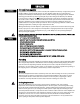
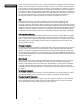
ENGLISH Description CS® 800H Power Amplifier Congratulations on your purchase of the CS 800H power amplifier from Peavey—designed for years of reliable, flawless operation under rigorous use. This amplifier offers the sonic superiority and unsurpassed reliability for which Peavey is famous, while remaining surprisingly compact. Advanced technology and extensive protection circuitry allow operation with greater efficiency into difficult loads and power conditions.
Operating Precautions Make sure the mains voltage is correct and is the same as that printed on the rear of the amplifier. Damage caused by connecting the amplifier to improper AC voltage is not covered by any warranty. See the Connecting Power section for more information on voltage requirements. Note: Always turn off and disconnect the amplifier from mains voltage before making audio connections. Also, as an extra precaution, have the attenuators turned down during power-up.
Connecting Inputs Input connections are made via the 3-pin XLR (pin 2+) or 6.3 mm plug “Combi” connectors on the rear panel of the amplifier. The inputs are actively balanced. Pinout and polarity of connection cables should be configured correctly (refer to the rear panel of the unit). The input overload point is high enough to accept the maximum output level of virtually any signal source. Connecting Outputs All models have two output (speaker) connections per channel.
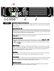
2 3 4 Front Panel 5 6 7 1 8 AC Power Switch/Circuit Breaker (1) The CS 800H amplifier has a combination AC switch/circuit breaker on the front panel. If the switch shuts off during normal use, push it back to the ON position once. If it will not stay on, the amplifier needs servicing. Input Attenuators (2) Whenever possible, set the attenuators fully clockwise to maintain optimum system headroom.
Active LED (7) The ACTIVE LED indicates that its channel’s output relay is closed and the channel is operational. In Bridge Mode, the Channel B LED goes off. Air Intake Vent (8) Cool air enters the amplifier here and exhausts through the rear vents. Any restriction or blockage could cause excessive operation temperatures and the unit could shut down.
Crossover Adjustment Knob (13) The CS 800H is equipped with two independent‚ two-way crossovers adjustable from 40 Hz to 300 Hz. These crossover frequencies are appropriate for use with a subwoofer system. The output of these crossovers is selected by the Amp Function switch and connected to the corresponding amplifier channel. Frequencies above the knob setting will be connected to the corresponding channel when the Amp Function switch is in the HIGH PASS position.
Protection Features The CS 800H incorporates several circuits to protect both itself and loudspeakers under virtually any situation. Peavey has attempted to make the amplifier as foolproof as possible by making it immune to short and open circuits, mismatched loads, DC voltage, and overheating. If a channel goes into the Distortion Detection or DDT gain reduction mode, the speaker load remains connected, but clipping percentage or output power are instantly reduced.
RampUp™ Signal Control Whenever amplifier powers up or comes out of a protect mode, the RampUp™ circuit activates. While the speakers are disconnected, the RampUp™ circuit fully attenuates the signal. After the output relay closes, the signal slowly and gradually raises up to its set level.
CS 800H Block Diagram Ch-A Hi Pass / Full Range Output HI PASS 2 3 Ch-A Input 1 Ch-A Amp Function Switch + - Ch-A Low Cut Switch Ch-A Input Attenuator Amplifier Protection Ch-A Power Amplifier Ch-A Output Relay 1 400 Watts 4 2 DDT LFC RampUp HI PASS Ch-A Output Ch-A Low Cut Adjust Ch-A Low Pass Output LO PASS Ch-A LEDs 12 Mode Switch Ch-B Hi Pass / Full Range Output HI PASS Ch-B Crossover Adjust 2 3 Ch-B Input 1 + - Ch-B Amp Function Switch Ch-B Low Cut Switch Ch-B Input Attenu
Glossary of Terms (Used in Setup Instructions) Stereo: Music with two separate channels‚ usually a left and right channel. Mono: Music with only one channel. Crossover: An electronic device that separates high and low frequencies and sends them to different outputs. The separate signals are usually sent to a high out and a low out. Bi-amp: The separation of high and low frequencies with a crossover‚ using separate speakers and power amps for each.
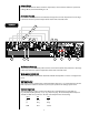
SETUP INSTRUCTIONS Stereo Operation 1 to STEREO. 1. Set AMP MODE switch 2. Set the A and B channel AMP FUNCTION switches 3. Connect the Left and Right program signal to the A and B channel inputs: 4. Connect the A and B channel speaker outputs 4 2 6 1 2 and 3 to FULL RANGE. 4 and 5 . 7 and 8 to the loudspeaker full range inputs. 5 3 7 9 8 Bridge Mode Operation 1 to BRIDGE. 1. Set AMP MODE switch 2. Connect the program signal to the A channel input 3.
9 5 2 3 4 7 1 8 6 10 11 Bi-Amp Operation (sub woofer & mid/high enclosure) 1 to STEREO. 1. Set AMP MODE switch 2. Set the A channel AMP FUNCTION switch 3. Turn on the A channel LOW CUT SWTICH 4. Set channel A LOW CUT frequency adjustment knob 4 to match the low frequency cut-off or the -3 dB down point of the sub woofer. (If you don’t know this specification‚ set it for 40 Hz.) 5. Set the channel A CROSSOVER frequency adjustment knob 100–150 Hz). 6.
Bi-amp Hookup Diagram RQ 4324 Q 215F CEL 2a Feedback Ferret II Kosmos CS 800H CS 800H SP2X SP2X SP 218 16 SP 218
C S® 8 0 0 H SPECIFICATIONS Rated output power (120 VAC, 60 Hz): Bridge mode, mono: 4 Ohms: 800 W @ 1 kHz, <0.1% THD 8 Ohms: 650 W @ 1 kHz, <0.1% THD Stereo mode, both channels driven: 2 Ohms: 400 W per channel 1 kHz, <0.05% THD 4 Ohms: 325 W per channel 1 kHz, <0.05% THD 8 Ohms: 225 W per channel 1 kHz, <0.
DEUTSCH Beschreibung CS 800H Verstärker Wir beglückwünschen Sie dazu, dass Sie sich für den CS 800H Verstärker von Peavey entschieden haben – er wurde für jahrelangen zuverlässigen und störungsfreien Einsatz unter harten Bedingungen entwickelt. Dieser Verstärker zeichnet sich durch die überragende Schallleistung und die einzigartige Zuverlässigkeit aus, für die Peavey bekannt ist. Gleichzeitig ist er überraschend kompakt.
Kühlanforderungen Der CS 800H Verstärker arbeitet mit einem Fremdkühlsystem, das eine niedrige gleichmäßige Betriebstemperatur gewährleistet. Luft wird durch die Ventilatoren auf der Vorderseite in den Verstärker eingesaugt, läuft durch die Kühlrippen der tunnelartigen Kanalkühlkörper und wird durch die seitlichen und rückseitigen Schlitze wieder abgegeben. Wird einer der Kühlkörper zu heiß, öffnet seine Sensorschaltung das Ausgangsrelais, wodurch die Last von diesem jeweiligen Kanal abgetrennt wird.
W I R E G A U G C H R T Stranded Wire Gauge (AWG) 5 18 .79 1.58 3.16 16 .50 1.00 2.00 14 .31 .62 1.24 12 .20 .40 .80 10 .125 .25 .50 40 . Power Loss into 2 Ohms (%) 18 1.58 3.16 6.32 16 1.00 2.00 4.00 14 .62 1.25 2.50 12 .40 .80 1.60 10 .25 .50 1.00 18 8.00 12.60 25.20 16 4.00 8.00 1.60 14 2.50 5.00 10.00 12 1.60 3.20 6.40 10 1.00 2.00 4.00 1.25 2.
Netzanschluss Der Leistungsbedarf des CS 800H Verstärkers ist auf 1/8 (übliche Musikbedingungen) und 1/3 (extreme Musikbedingungen) ausgelegt. Der Nennwert der Starkstromaufnahme wird nur über den Sicherungsautomaten auf der Vorderseite begrenzt. Den Leistungsbedarf des Verstärkers können Sie den technischen Daten in dieser Anleitung entnehmen. Achten Sie darauf, dass die Netzspannung korrekt ist und mit den Angaben auf der Rückseite des Verstärkers übereinstimmt.
2 3 4 5 Funktionen an der Vorderseite 6 7 1 8 Wechselstrom-Netzschalter/Sicherungsautomat (1) Der CS 800H Verstärker ist mit einem kombinierten Wechselstrom-Netzschalter bzw. Sicherungsautomaten auf der Vorderseite ausgestattet. Schaltet sich der Schalter während des Normalbetriebs aus, drücken Sie ihn einmal in die Position ON zurück. Schaltet er sich erneut aus, muss der Verstärker gewartet werden.
der bzw. die Lautsprecher aufgrund von Überhitzung abgetrennt werden. Ist die Temperatur des Kanals wieder auf einen betriebssicheren Wert gesunken, erlischt die LED, und der bzw. die Lautsprecher werden wieder angeschlossen. DDT-Active-LED (6) Sie leuchtet auf, wenn die DDT-Kompression aktiv ist. Steht der Schalter zur Aktivierung/ Deaktivierung auf Deaktivierung, zeigt die LED an, wenn Clipping bzw. Verzerrung auftritt.
Kanaleingang (12) Dieser Eingang ist mit einem Combo-Stecker ausgestattet, der für einen herkömmlichen dreipoligen männlichen XLR-Stecker, einen 6,3-mm-Klinkenstecker oder einen 6,3-mm- Monostecker geeignet ist. Daneben steht ein elektronisch symmetrierter Eingang mit XLR- und 6,3-mm-Klinkenanschluss zur Verfügung.
Speakon®-Ausgangsstecker (19) Jeder Kanal ist mit einem vieradrigen Speakon-Stecker für den Ausgang ausgestattet. Bei beiden Kanälen ist der Stift 1+ der Kanalsignalausgang und der Stift 1- die Gehäuseerdung. Beim Stecker von Kanal A liegt am Stift 2+ der Signalausgang von Kanal B an, und der Stift 2- ist die Gehäuseerdung. Anschlussklemmen-Ausgangsstecker (20) Jeder Kanal ist mit einem Paar schutzisolierter Anschlussklemmen ausgestattet, die parallel zum Speakon-Stecker angeschlossen sind.
Kanal unabhängig selbst, indem er seine Last abtrennt und sich abschaltet, bis er wieder abgekühlt ist. Solange leuchtet die TEMP-LED des Kanals auf. Zudem erlischt währenddessen die ACTIVE-LED, TEMP- und DDT-LED leuchten aber weiterhin, und die Kühlventilatoren laufen mit hoher Drehzahl weiter. Kurzschluss Wird ein Ausgang kurzgeschlossen, schützt die LFC-Schaltung den Verstärker automatisch.
Passbandnennwerten. Achten Sie unbedingt darauf, dass die niedrigen und mittleren Bänder einer elektronischen Frequenzweiche an die korrekten Verstärker und Treiber und nicht versehentlich an die für ein Band mit niedrigerer Frequenz angeschlossen werden. Der Clipping-Punkt eines Verstärkers ist seine maximale Spitzenausgangsleistung, und der Peavey CS 800H Hochleistungsverstärker kann eine höhere Leistung bringen, als viele Lautsprecher ohne Schäden bearbeiten können.
Erklärung der Begriffe (für die Setup-Anweisungen) Stereo: Musik mit zwei getrennten Kanälen, in der Regel einem linken und einem rechten Kanal. Mono: Musik mit nur einem Kanal. Frequenzweiche: Eine elektronische Vorrichtung, die hohe und niedrige Frequenzen trennt und sie an verschiedene Ausgänge sendet. Die getrennten Signale werden in der Regel an einen High-Ausgang und einen LowAusgang gesendet.
Setup-Anweisungen Stereobetrieb 2. 1 auf STEREO stellen. AMP-FUNCTION-Schalter 2 und 3 von Kanal A und B auf FULL RANGE stellen. 3. Left- und Right-Programmsignal an Eingänge 4. Lautsprecherausgänge 1. AMP-MODE-Schalter 4 2 6 4 und 5 von Kanal A und B anschließen. 7 und 8 von Kanal A und B an Full-Range-Eingänge des Lautsprechers anschließen. 1 5 3 7 9 8 Betrieb im Bridge-Modus 1. 2. 3. 1 auf BRIDGE stellen. Programmsignal an Eingang 4 von Kanal A anschließen.
9 5 2 3 4 7 1 8 6 10 11 Mono-Biamp-Betrieb (Subwoofer und Mid/High-Box) 1 auf STEREO stellen. 1. AMP-MODE-Schalter 2. AMP-FUNCTION-Schalter 3. LOW CUT 4. Den LOW-CUT-Frequenzeinstellknopf 4 von Kanal A entsprechend der Niedergrenzfrequenz oder dem -3 dBAbsenkpunkt des Subwoofers einstellen. (Wenn diese Daten nicht bekannt sind, auf 40 Hz einstellen.) 5. CROSSOVER-Frequenzeinstellknopf Regel 100-150 Hz). 6. AMP-FUNCTION-Schalter 7.
C S® 8 0 0 H SPECIFICATIONS Rated output power (120 VAC, 60 Hz): Bridge mode, mono: 4 Ohms: 800 W @ 1 kHz, <0.1% THD 8 Ohms: 650 W @ 1 kHz, <0.1% THD Stereo mode, both channels driven: 2 Ohms: 400 W per channel 1 kHz, <0.05% THD 4 Ohms: 325 W per channel 1 kHz, <0.05% THD 8 Ohms: 225 W per channel 1 kHz, <0.
ESPAÑOL Description Amplificador de Poder CS 800H Felicidades en tu compra de un amplificador CS 800H de Peavey, diseñado para brindarte años de operación confiable bajo el uso más exigente. Este amplificador ofrece superioridad sonora y la confiabilidad inmejorable que por tanto años ha sido relacionada con Peavey, manteniendo un tamaño compacto. Tecnología avanzada y extensos circuitos de protección permiten la operación a gran eficiencia en condiciones no siempre perfectas, y con cargas pesadas.
Requisitos de enfriamiento. El amplificador CS 800H usa un sistema de enfriamiento de aire forzado que mantiene una temperatura de operación baja y uniforme. El aire se mete al amplificador por medio de ventiladores en el panel frontal, viaja por las aletas de enfriamiento de las parrillas de enfriamiento, y luego sale por las aperturas en la parte trasera y laterales. Si se llegara a calentar la parrilla de enfriamiento su circuito de seguridad desconectará la carga del canal específico.
W I R E G A U G C H R T Stranded Wire Gauge (AWG) 5 18 .79 1.58 3.16 16 .50 1.00 2.00 14 .31 .62 1.24 12 .20 .40 .80 10 .125 .25 .50 40 . Power Loss into 2 Ohms (%) 18 1.58 3.16 6.32 16 1.00 2.00 4.00 14 .62 1.25 2.50 12 .40 .80 1.60 10 .25 .50 1.00 18 8.00 12.60 25.20 16 4.00 8.00 1.60 14 2.50 5.00 10.00 12 1.60 3.20 6.40 10 1.00 2.00 4.00 1.25 2.
Conectando Corriente Los requisitos de corriente del amplificador CS 800H han sido medidos a 1/8 de poder (condiciones de música típicas) y 1/3 de poder (condiciones de música extremas). La máxima necesidad de corriente es limitada sólo por el breaker en el panel frontal. Consulta las especificaciones de este manual para cifras de corriente que este amplificador demanda. Hay que asegurarse que el voltaje es el correcto y es el mismo que el impreso en la parte trasera del amplificador.
2 3 4 5 Panel Frontal 6 7 1 8 Interruptor de Corriente/Breaker de Circuito (1) El amplificador CS 800H cuenta con una combinación de Interruptor de Corriente/Breaker en el panel frontal. Si el interruptor se apaga durante la operación normal, oprímelo a la posición de encendido (ON) una vez más. Si no se queda en esa posición requiere servicio.
LED de TEMP (5) El LED de TEMP se ilumina para indicar que el relay de salida del canal está abierto, desconectando los parlantes por una condición de calentamiento. Una vez que la temperatura del canal haya vuelto a un nivel de operación segura el LED se apagará y los parlantes serán reconectados. LED de actividad DDT (6) Se ilumina cuando existe compresión DDT. Con el interruptor de activo/desactivado en la posición de desactivado, el LED indica cuando hay distorsión.
Interruptor DDT (11) Este interruptor es usado para encender o apagar la compresión DDT. Se recomienda que se mantenga l compresión DDT encendida todo el tiempo para proteger los parlantes de ondas cuadradas. Entrada de Canal (12) Esta entrada cuenta un conectador combo que acepta XLR estándar de tres agujas, 1/4" (6.3 mm) TRS, ó 1/4" mono. Se provee una entrada balanceada electrónicamente vía conectadores TRS y XLR.
amplificador secundario. Si el interruptor de función del amplificador está en posición HIGH PASS, la porción de frecuencias agudas del crossover estará presente en el conectador. Si el interruptor de función del amplificador está en la posición FULL RANGE (rango completo) o LOW PASS, el crossover no estará activo y se permitirá la conexión de la señal de rango completo a un amplificador secundario.
Limitación de Detección de Distorsión En cualquier momento que un canal produzca mucha energía, o saturación continua, el circuito DDT automáticamente reduce la ganancia del canal a un nivel justo por debajo de la saturación, protegiendo a los parlantes contra ondas cuadradas continuas que se pueden producir. Las situaciones que pueden activar el circuito DDT incluyen retroalimentación descontrolada, oscilaciones, o una instalación incorrecta o una falla en la corriente del amplificador.
Protección de Encendido/Apagado Durante el encendido el amplificador se mantiene en modo de protección, con las salidas desconectadas, por aproximadamente cuatro segundos mientras que la fuente de poder se carga y estabiliza. Mientras los relays de salida están abiertos, el LED de DDT se encenderá. Cuando se quita la corriente, las cargas de los parlantes se desconectan inmediatamente para evitar los ‘pops’ y ‘tumps’.
Glosario de Términos (Usado en Instrucciones de Instalación) Estéreo: Música con dos canales separados, usualmente derecho e izquierdo. Mono: Música con sólo un canal Crossover: Un aparato electrónico que separa las frecuencias graves y agudas y las envía a diferentes salidas. Las señales separadas generalmente son enviadas a una salida grave y una aguda. Bi-amp: La separación de frecuencias graves y agudas sin crossover, usando parlantes diferentes y amplificadores para cada una.
Setup-Anweisungen Operación Puente/Mono 1 auf STEREO stellen. 1. AMP-MODE-Schalter 2. AMP-FUNCTION-Schalter 3. Left- und Right-Programmsignal an Eingänge 4. Lautsprecherausgänge 4 2 6 2 und 3 von Kanal A und B auf FULL RANGE stellen. 4 und 5 von Kanal A und B anschließen. 7 und 8 von Kanal A und B an Full-Range-Eingänge des Lautsprechers anschließen. 1 5 3 7 9 8 Operación de Dos Canales Paralelos (Rango Completo) 1 a BRIDGE 1. Ajustar el interruptor AMP MODE 2.
9 5 2 3 4 7 1 8 6 10 11 Operación Mono Bi-Amp 1 a STEREO 1. Ajustar el interruptor AMP MODE 2. Ajustar el interruptor A AMP FUNCTION 3. Encender el LOW CUT del canal A, 4. Ajustar la frecuencia de recorte (LOW CUT) del canal A con la perilla 4 para igualar la frecuencia de recorte de graves o el punto de -3 dB del subwoofer. (Si no sabes esta especificación, ajústalo para 40 Hz). 5. Ajusta la frecuencia de CROSSOVER del canal A, perilla 150 Hz) 6.
C S® 8 0 0 H SPECIFICATIONS Rated output power (120 VAC, 60 Hz): Bridge mode, mono: 4 Ohms: 800 W @ 1 kHz, <0.1% THD 8 Ohms: 650 W @ 1 kHz, <0.1% THD Stereo mode, both channels driven: 2 Ohms: 400 W per channel 1 kHz, <0.05% THD 4 Ohms: 325 W per channel 1 kHz, <0.05% THD 8 Ohms: 225 W per channel 1 kHz, <0.
FRANÇAIS Description Amplificateurs de Puissance CS 800H Félicitations d’avoir choisi un amplificateur de puissance Peavey CS 800H. Ces unités sont concues pour vous permettre une utilisation intensive sans problèmes de fiabilité ou d’utilisation. Le tout dans une unité compacte, ils proposent une circuiterie de pointe et des systèmes de protection qui ont fait la renommée de Peavey.
Précautions d’Utilisation Assurez vous que l’alimentation électrique est correcte pour votre unité (une étiquette précise les voltages et consommation de votre unité, située sur sa face arrière). Aucune garantie ne couvre les dommages créés à une unité par une lauvaise connection d’alimentation. Reportez-vous au paragraphe’Alimentation Electrique’ pour plus d’informations sur ce sujet.
Connecter les entrées de votre unité (Inputs) Les connexions d’entrées sont des combo XLR / 1/4"Jack (acceptent les 2 standarts sur la même connexion). Les entrées sont activement symétrisées. Vérifiez que vos autres unités partagent la même norme de connexion (annotées sur l’arrière de votre unité). La sensibilité d’entrée de votre CS lui permettra de s’accomoder de la plupart des signaux.
2 3 4 5 Panneau Avant 6 7 1 8 AC Power Switch/Circuit Breaker (1) Il y a un disjoncteur dans chaque unité. Il permet de limiter l’alimentation électrique et éviter toute surchauffe ou possible panne due à une mauvaise connection. La valeur de ce disjoncteur a été choisie pour permettre à votre unité de fonctionner normalement tout en protégeant votre unité. Son déclenchement ne devrait pas parvenir en utilisation normale, et indique qu’un courant trop important est drainé par votre unité.
TEMP LED (5) Cette Led s’illumine pour vous indiquer que la protection de ce canal a déconnecté ses sorties due à la détection d’une température de fonctionnement trop élevée. Dès que la température du canal concerné atteindra une valeur acceptable, cette Led s’éteindra et les sorties seront reconnectées. DDT LED (6) Ces indicateurs s’illuminent lorsque la compression DDT travaille sur le signal. Cette illumination doit rester intermittente pour éviter une déformation audible du signal.
LOW CUT Switch (12) Ce sélecteur vous permet d’engager (position enfoncée) ou de désengager (position sortie) le filtre coupe-bas du canal concerné. HIGH PASS/FULL RANGE OUTPUT Connector (13) La fonction de cette sortie dépend de la position du sélecteur de mode correspondant (9). En mode Low-Pass, il permet de récupérer les hautes fréquences du signal de l’entrée; en mode Low Pass et Full Range, le signal complet est présent pour vous permettre de chainer plusieurs amplificateurs.
Protection de Mise Sous/Hors Tension A l’allumage, votre unité se mettra toujours en mode de protection, avec les sorties déconnectées pour a peu près 4 secondes (temps de stabilisation des composants). La Led DDT s’illumine pour vous indiquer cet état. En cas de mise hors tension, les sorties se disconnectent immédiatement pour éviter tout bruit parasite dans les enceintes.
Glossaire Stereo: Musique composé de deux signaux indépendants (droite et gauche) Mono: Musique composé d’un seul signal Crossover: Unité électronique permettant de séparer un signal en fonction de sa fréquence. Les deux signaux ainsi obtenus comprennent pour l’un les bassses fréquences, pour l’autre les hautes fréquences. Bi-amp: Utilisation d’un filtre actif (Crossover) pour séparer le signal, puis d’amplificateurs et d’enceintes dédiés à chaques parties de ce signal.
Setup-Anweisungen Stereo Operation 1 to STEREO. 1. Set AMP MODE switch 2. Set the A and B channel AMP FUNCTION switches 3. Connect the Left and Right program signal to the A and B channel inputs: 4. Connect the A and B channel speaker outputs 4 2 6 1 2 and 3 to FULL RANGE. 4 and 5 . 7 and 8 to the loudspeaker full range inputs. 5 3 7 9 8 Bridge Mode Operation 1 to BRIDGE. 1. Set AMP MODE switch 2. Connect the program signal to the A channel input 3.
9 5 2 3 4 7 1 8 6 10 11 Bi-Amp Operation (sub woofer & mid/high enclosure) 1 to STEREO. 1. Set AMP MODE switch 2. Set the A channel AMP FUNCTION switch 3. Turn on the A channel LOW CUT SWTICH 4. Set channel A LOW CUT frequency adjustment knob 4 to match the low frequency cut-off or the -3 dB down point of the sub woofer. (If you don’t know this specification‚ set it for 40 Hz.) 5. Set the channel A CROSSOVER frequency adjustment knob 100–150 Hz). 6.
C S® 8 0 0 H SPECIFICATIONS Rated output power (120 VAC, 60 Hz): Bridge mode, mono: 4 Ohms: 800 W @ 1 kHz, <0.1% THD 8 Ohms: 650 W @ 1 kHz, <0.1% THD Stereo mode, both channels driven: 2 Ohms: 400 W per channel 1 kHz, <0.05% THD 4 Ohms: 325 W per channel 1 kHz, <0.05% THD 8 Ohms: 225 W per channel 1 kHz, <0.
NOTES: 57
NOTES: 58
PEAVEY ELECTRONICS CORPORATION LIMITED WARRANTY Effective Date: July 1, 1998 What This Warranty Covers Your Peavey Warranty covers defects in material and workmanship in Peavey products purchased and serviced in the U.S.A. and Canada.
Features and specifications subject to change without notice. Peavey Electronics Corporation • 711 A Street • Meridian • MS • 39301 (601) 483-5365 • FAX (601) 486-1278 • www.peavey.com ©2003 80304955 Printed in the U.S.A.