-- -- - - 212 Single Unit Guitar Amp
A A Intended to alert the user to the presence of uninsulated “dangerous voltage” within the product’s enclosure that may be of sufficient magnitude to constitute a risk of electric shock to persons. Intended to alert the user to the presence of important operating and maintenance (servicing) instructions in the literature accompanying the product. CAUTION Risks of electrical shock - DO NOT OPEN CAUTION To reduce the risk of electric shock, do not remove cover. No user serviceable parts inside.
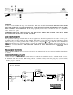
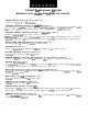
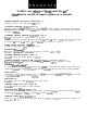
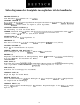
FRONT PANEL 3 NORMAL 12 13 - @ s~~~LE~~~~~~~:~~~:~~~~~~~~~~~~~:~~a~~~~~*~~~~~ ON ON 1 2 PILOT PRESENCE 4 5 VOLUME TREBLE MIDDLE 6 BASS REVERB 8 7 1 12 1 12 1 12 1 12 1 12 1 12 1 12 1 12 1 12 POST PRE NORMAL 9 10 11 B&O& INPUTS POWER SWITCH (1) Switch to “on” position to turn on. STANDBY SWITCH (2) Allows amp to be placed in standby or active mode. In standby mode the tubes remain hot, but the amplifier is not operational.
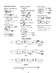
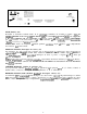
REAR PANEL 16 FUSE (14) The fuse is located within the cap of the fuseholder. If the fuse should fail, IT MUST BE REPLACED WITH THE SAME TYPE AND VALUE IN ORDER TO AVOID DAMAGE TO THE EQUIPMENT AND TO PREVENT VOIDING THE WARRANTY. If the amp repeatedly blows fuses, it should be taken to a qualified service center for repair. WARNING: THE FUSE SHOULD ONLY BE REPLACED WHEN THE POWER CORD HAS BEEN DISCONNECTED FROM ITS POWER SOURCE.
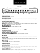
SPECIFICATIONS PREAMP SECTION POWER AMPLIFIER SECTION 4 - 6BQYEL84’s with 12AX7 driver Rated Power & Load: 50 W RMS into 16 or 8 ohms Power @ Clipping: (Typically) (5% THD, 1 kHz, 120 V AC line) 50 W RMS into 16 or 8 ohms (Bias must be reduced to measure) Frequency Response: +0, -2 dB, 50 Hz to 15 kHz, @ 40 W RMS into 16 ohms Hum & Noise: Greater than 80 dB below rated power Power Consumption: 200 watts, 50/60 Hz, 120 V AC (Domestic) 2 - 12AX7’s The following specs are measured @ 1 kHz with the cont
Consulte 10s diagramas de1 panel delantero en la seccih de inglb de este manual. POWER SWITCH (Interruptor de corriente) (1) Coloque a la position “on” para encender. STANDBY SWITCH (Interruptor de condicih de espera) (2) Este interruptor le permite a su aparato estar en condition de“espera” o la condition de active. En la condicion “standby” 10s tubos permanecen calientes, pero el amplificador no esta en operation.
FUSE (Fusible) (14) El fusible se encuentra localizado dentro de la capsula de1 portafusible. Si el fusible se quema o falla, SE DEBERA REEMPLAZAR CON UN0 DEL MISMO TIP0 Y VALOR, PARA EVITAR DAfiO AL APARATO Y EL ANULAMIENTO DE LA GARANTIA. Si el aparato quema 10s fusible repetidamente, cerciorese de que esta conectado a un tomacorriente con el voltaje adecuado, si esto es correcto, entonces desconectelo y llevelo a revision por un tecnico autorizado.
Veuillez vous r6f6rer au “front panel line art”’ situ6 dans la section en langue anglaise de ce manuel. POWER SWITCH (Interrupteur d’alimentation) (1) Mettre en position “On” pour mettre sous tension. STANDBY SWITCH (S,electeur attente) (2) Permet de selectionner l’etat de l’ampli: mode “Active” (actif) ou mode “Standby” (attente). En position “Standby”, l’amplificateur ne fonctionne pas mais les lampes (“tubes”) restent chaudes pour permettre de le remettre en service sans delai.
FUSE (Fusible) (14) Le fusible se trouve a l’interieur de son support. Si le fusible grille, IL DOIT ETRE REMPLACE PAR UN FUSIBLE DE MEME TYPE ET MEME VALEUR POUR EVITER TOUT DOMMAGE A LAPPAREIL ET EVITER D’ANNULER LA GARANTIE. Si le fusible grille de fqon rep&e, apportez l’appareil a un centre de service qualifie pour reparation. AVERTISSEMENT: LE FUSIBLE NE DOIT ETRE REMPLACE QUE LORSQUE LE CORDON D’ALIMENTATION EST DE BRANCHE DE LA SOURCE D’ALIMENTATION.
Siehe diagramm der frontplatte im englischen teil des handbuchs. POWER SWITCH (1) Zum Einschalten diesen Schalter auf “on” stellen. STANDBY SWITCH (2) Ermiiglicht es, den Verstarker mit abgeschaltetem Tonsignal betriebsbereit zu halten. In der “Standby”Betricbsart werden die Riihren weiter beheizt, das Signal ist jedoch abgeschaltet. CHANNEL SELECT SWITCH (3) Zur Umschaltung von Lead auf Normal Kanal. MERKE: Kanalwahl kann such mittels dem Fernbedienungsfuflschalter ausgefuhrt werden.
FUSE (14) Die Sicherung befindet sich innerhalb der Kappe des Sicherungshalters. Wenn die Sicherung durchbrennt, MUSS SIE DURCH EINE DES GLEICHEN TYPS UND MIT DEM GLEICHEN WERT ERSETZT WERDEN, UM DAS GERAT ZU SCHUTZEN UND DIE GARANTIELEISTUNGEN ZU ERHALTEN. Wenn am Verstarker wiederholt die Sicherung durchbrennt, muB das Getit in eine qualifizierte Fachwerkstatt.
THIS LIMITED WARRANTY VALID ONLY WHEN PURCHASED AND REGISTERED IN THE UNITED STATES OR CANADA. ALL EXPORTED PRODUCTS ARE SUBJECT TO WARRANTY AND SERVICES TO BE SPECIFIED AND PROVIDED BY THE AUTHORIZED DISTRIBUTOR FOR EACH COUNTRY. Ces clauses de garantie ne sont vaiables qu’aux Etats-Unis et au Canada. Dans tour les autres pays, les clauses de garantie et de maintenance sont fixees par le distributeur national et assuree par lul seion la legislation envigueur.
IMPORTANT SAFETY INSTRUCTIONS WARNING When using electric products, basic cautions should always be followed, including the following. 1. Read all safety and operating instructions before using this product. 2. All safety and operating instructions should be retained for future reference. 3. Obey all cautions in the operating instructions and on the back of the unit. 4. All operating instructions should be followed. 5. This product should not be used near water, i.e.
Features and specifications subject to change without notice. 01992 A(H) Peavey Electronics Corporation 711 A Street / Meridian, MS 39301 / U.S.A. / (601) 483-5365 / Fax 486-1278 #80301444 Printed in U.S.A.