FIREBASS 700 ™ 7 0 0 Wa t t B a s s A m p l i f i c a ti o n O p e ra t i n g G u i d e
Intended to alert the user to the presence of uninsulated "dangerous voltage" within the product's enclosure that may be of sufficient magnitude to constitute a risk of electric shock to persons. Intended to alert the user of the presence of important operating and maintenance (servicing) instructions in the literature accompanying the product. CAUTION: Risk of electrical shock – DO NOT OPEN! CAUTION: To reduce the risk of electric shock, do not remove cover. No user serviceable parts inside.
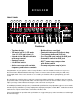
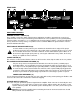
ENGLISH FRONT PANEL 1 3 2 4 5 6 13 12 14 15 7 8 9 18 10 16 17 22 23 11 26 24 25 20 21 19 Features: • Top box design • 700 watts into 2 Ω, 475 watts into 4 Ω, 275 watts into 8 Ω • 3-band active EQ with shiftable mid-range control • Contour control • -10 dB Pad switch • Active crossover with variable frequency and balance controls Buffered tuner send jack Footswitchable post-EQ effects loop Transformer balanced XLR jack Pre-/Post-EQ send switch for XLR jack Ground lift switch for XLR ja
FIREBASS™ 700 FRONT PANEL FEATURES INPUT JACK (1) This input will accept signals from all types of bass pickups. INPUT PAD SWITCH (2) Provided for instruments that have extremely high output, which can result in overdriving (distorting) the input stage. Depressing the switch to its “in” or “active” position reduces the level of the input signal by 10 dB. TUNER SEND JACK (3) A 1/4" jack is provided for connecting an instrument tuner.
EFFECTS RETURN JACK (17) Input for returning signals from external low-level effects or signal processing equipment. EFFECTS LOOP REMOTE SWITCH JACK (18) This jack accommodates the remote footswitch (optional part number 00051000 ON/OFF single button switch), which is used to remove the effects loop from the signal path. The remote footswitch essentially acts as a bypass to punch in or punch out from your external effects.
REAR PANEL 27 28 29 32 31 31 30 REAR PANEL FEATURES GROUND POLARITY SWITCH (27) Three position, rocker-type switch, which for most applications should be operated in the center (zero) position. If hum or noise is present with the ground switch in the center position, place the ground polarity switch to positive or negative (+ or -) to minimize hum; should a problem continue, consult your authorized Peavey dealer, the Peavey factory, or a qualified service technician.
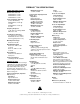
FIREBASS™ 700 SPECIFICATIONS POWER AMPLIFIER SECTION Rated Power and Load: 700W RMS into 2 ohms 475W RMS into 4 ohms 275W RMS into 8 ohms Power @ Clipping (Typically): (1 kHz, 120 VAC line) 490W RMS into 4 ohms @ 1% THD 550W RMS into 4 ohms @ 5% THD Frequency Response: -1 dB, 20 Hz to 30 kHz @ 400W RMS into 4 ohms Total Harmonic Distortion: Less than 0.25%, 100 mW to 450W RMS, 20 Hz to 10 kHz, 4 ohms (typically below 0.
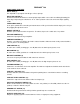
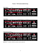
™ Firebass 700 Recommended Settings Rock Setting your preference your preference OUT Slap Setting your preference doesn't matter when Mid is set to 0 your preference IN Blues/Country Setting your preference your preference OUT NOTE: DDT™ should be utilized for maximum speaker protection 9
E S PA Ñ O L Consulte los diagramas del panel delantero en la sección de inglés de este manual.
FIREBASS™ 700 FUNCIONES DEL PANEL FRONTAL ENCHUFE HEMBRA DE ENTRADA (1) Esta entrada acepta la conexión de señales de todo tipo de micrófonos de bajos. INTERRUPTOR DE ATENUADOR FIJO DE ENTRADA (2) Este interruptor se utiliza para los instrumentos con niveles de salida extremadamente altos, que pueden sobreexcitar (distorsionar) la etapa de entrada. Para reducir en –10 dB el nivel de la señal de entrada, oprima el interruptor para llevarlo hacia adentro (posición activa).
ENCHUFE HEMBRA PARA EL INTERRUPTOR REMOTO DEL CIRCUITO DE EFECTOS (18) Este enchufe hembra permite conectar el conmutador de pedal remoto (opcional, número de parte 00051000, interruptor de botón único con encendido y apagado), que se usa para eliminar el circuito de efectos del circuito de señales. Fundamentalmente, el conmutador de pedal remoto actúa como derivación para activar o desactivar los efectos externos.
PANEL POSTERIOR 27 31 28 29 32 31 30 FUNCIONES DEL PANEL POSTERIOR CONMUTADOR DE POLARIDAD DE TOMA DE TIERRA (27) Este conmutador es oscilante y tiene tres posiciones. Para la mayoría de las aplicaciones debe ser operado en la posición media (cero). Si se detectan zumbidos o ruidos cuando el conmutador de toma de tierra se encuentra en la posición media, lleve el conmutador de polaridad a la posición positiva (+) o negativa (–) para minimizar el zumbido.
FIREBASS™ 700 ESPECIFICACIONES Aviso: Para impedir el recalentamiento del amplificador, el ventilador frontal y las aberturas posteriores de la unidad deben mantenerse siempre libres de obstrucciones.
FRANÇAIS Veuillez-vous référer au « front panel » art situé dans la section en langue anglaise de ce manuel.
FIREBASS™ 700 FACE AVANT ENTRÉE JACK (1) Cette entrée fonctionne pour tous les types de basses. SÉLECTEUR D'ENTRÉE (2) Cet atténuateur est destiné aux instruments à haut niveau de sortie pouvant causer une saturation (distorsion) indésirable. En plaçant le sélecteur dans sa position “in” ou “active” le niveau du signal d'entrée est réduit de 10 dB. SORTIE TUNER (3) Une prise jack est fournie pour une sortie accordeur.
SORTIE EFFECTS SEND (16) Sortie fournissant un signal bas niveau pour des effets ou processeurs externes. ENTRÉE EFFECTS RETURN (17) Retour des signaux bas niveau provenant d'effets ou processeurs externes. PRISE DE PÉDALE DE COMMANDE DE LA BOUCLE D'EFFET (18) Cette prise est destinée au footswitch (optionel simple action ref n°00051000) retirant la boucle d'effet du chemin du signal. La pédale de commande permet d'engager et désengager vos effets externes.
FACE ARRIÈRE 27 31 28 29 32 31 30 PANNEAU ARRIÈRE SÉLECTEUR DE POLARITÉ DE LA MASSE (27) Absent sur les versions Européennes. DISJONCTEUR RESET/CIRCUIT BREAKER (28) Utilisez ce bouton-poussoir pour remettre en fonction votre amplificateur si le disjoncteur a sauté. Eteignez d'abord l'amplificateur avant de réarmer le disjoncteur. Pressez le bouton. Allumez l'appareil et assurez-vous que la LED de mise sous tension est allumée.
FIREBASS™ 700 SPECIFICATIONS POWER AMPLIFIER SECTION Rated Power and Load: 700W RMS into 2 ohms 475W RMS into 4 ohms 275W RMS into 8 ohms Power @ Clipping (Typically): (1 kHz, 120 VAC line) 490W RMS into 4 ohms @ 1% THD 550W RMS into 4 ohms @ 5% THD Frequency Response: -1 dB, 20 Hz to 30 kHz @ 400W RMS into 4 ohms Total Harmonic Distortion: Less than 0.25%, 100 mW to 450W RMS, 20 Hz to 10 kHz, 4 ohms (typically below 0.1%) DDT™ Dynamic Range: Greater than 20 dB DDT™ Maximum THD: Below 0.
DEUTSCH Siehe Diagramm der Frontplatte im englischen Teil des Handbuchs.
FIREBASS™ 700 FRONT PANEL FEATURES EINGANGSBUCHSE (1) Dieser Eingang akzeptiert Signale von allen Bass Pickup Typen. INPUT PAD SCHALTER (2) Vorgesehen für Instrumente mit extrem hohen Output, was zur Übersteuerung (Verzerrung) des Input Stages führen kann. In der Stellung “In” oder “Aktiv” (Tastschalter reingedrückt) wird der Pegel des Eingangssignals um 10 dB abgesenkt. TUNER SENDEBUCHSE (3) Eine 1/4" Buchse ist für den Anschluß eines Instrumenten Tuners vorgesehen.
EFFEKT RETURN BUCHSE (17) Eingang für die Signal Rückleitung externer Effekte mit Niedrigpegel oder Signalverarbeitungs-Equipment. EFFEKT LOOP REMOTE SCHALTERBUCHSE (18) Diese Buchse dient der Aufnahme des Remote Fußschalters (optionale Teilenummer 00051000 ON/OFF), der benutzt wird, um die Effekt Loop vom Signalpfad zu entfernen. Dieser Fußschalter agiert als Bypass für einen Punch In oder Punch Out Ihrer externen Effekte.
RÜCKSEITE 27 31 28 29 32 31 30 FEATURES DER RÜCKSEITE MASSE POLARITÄTSSCHALTER (27) Positionsschalter mit 3 Stellungen. Dieser befindet sich für die meisten Anwendungen in seiner Mittelstellung (0). Ist Brummen oder Rauschen trotz Mittelstellung weiterhin vorhanden, wechseln Sie die Schalterposition auf positiv oder negativ (+ oder -), um das Brummen zu minimalisieren. Ist das Problem damit nicht behoben, suchen Sie einen autorisierten Peavey Händler oder einen qualifizierten Service-Techniker auf.
FIREBASS™ 700 SPEZIFIKATIONEN LEISTUNGSVERSTÄRKER BEREICH Nennstrom und Belastung: 700W RMS an 2 Ohm 475W RMS an 4 Ohm 275W RMS an 8 Ohm Leistung beim Clipping (Typisch): (1 kHz, 120 VAC Linie) 490W RMS an 4 Ohm bei 1% THD 550W RMS an 4 Ohm bei 5% THD Frequenzreaktion: -1 dB, 20 Hz bis 30 kHz bei 400W RMS an 4 Ohm Total Harmonic Distortion (THD): Weniger als 0.25%, 100 mW bis 450W RMS, 20 Hz bis 10 kHz, 4 Ohm (gewöhnlich unter 0.1%) DDT™ Dynamikbereich: Größer als 20 dB DDT™ Maximale THD: Unter 0.
NOTES 25
NOTES 26
PEAVEY ELECTRONICS CORPORATION LIMITED WARRANTY Effective Date: July 1, 1998 What This Warranty Covers Your Peavey Warranty covers defects in material and workmanship in Peavey products purchased and serviced in the U.S.A. and Canada.
IMPORTANT SAFETY INSTRUCTIONS WARNING: When using electric products, basic cautions should always be followed, including the following: 1. Read all safety and operating instructions before using this product. 2. All safety and operating instructions should be retained for future reference. 3. Obey all cautions in the operating instructions and on the back of the unit. 4. All operating instructions should be followed. 5. This product should not be used near water, i.e.