™ GPS Series Amplif ier s OPERATING GUIDE
Intended to alert the user to the presence of uninsulated “dangerous voltage” within the product’s enclosure that may be of sufficient magnitude to constitute a risk of electric shock to persons. Intended to alert the user of the presence of important operating and maintenance (servicing) instructions in the literature accompanying the product. CAUTION: Risk of electrical shock — DO NOT OPEN! CAUTION: To reduce the risk of electric shock, do not remove cover. No user serviceable parts inside.
ENGLISH GPS™ SERIES POWER AMPLIFIERS Congratulations on your purchase of the new GPS Series amplifier by Peavey Electronics. Years of power amp design and testing have produced a totally refined, dynamic power amp product line. The GPS Series consists of the GPS 900, GPS 1500, GPS 2600, GPS 3400 and GPS 3500. Each model features tunnel cooling, two variable-speed fans, initialization protection and DDT™ speaker protection.
Please read this guide in its entirety. Pay close attention to the various warnings within as they pertain to the safety of you and your product. Each section will begin with a short description of the information you can expect to obtain within. This should help you to locate the material you are looking for in a timely manner. Once again, congratulations and thank you for buying Peavey! UNPACKING/REGISTRATION Inspect the amplifier during unpacking. If you find any damage, notify your dealer immediately.
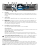
2. AC POWER SWITCH (Located on the front of the unit. See diagram on page 9.) A two-position power switch is on the right side of the front panel. With the top portion of the switch pushed to the “IN” position the amplifier is “ON”. Press the bottom portion of the switch to the “IN” position to turn the unit “OFF”. 3. POWER LED (Located on the front of the unit. See diagram on page 9.) The Power LEDs illuminate to indicate the amplifier is turned on.
“bridge” mode, place the Mode Switch to the “in” position where the switch remains down. The amp is now a mono amplifier and only requires a single input. Plug your input signal into Channel A only for “bridge” mode operation. Channel B input must not have anything connected. NOTE FOR GPS 900 AND 1500: When these models are switched to “bridge” mode, the Power LED (3) for Channel B will no longer illuminate.
loudspeaker enclosures associated with this power amplifier must be in phase with any other loudspeaker enclosures associated with other power amps. If one loudspeaker system were to “push” while the other “pulls”, a serious sound “cancellation” could result. Changing the setting of the polarity switch has the same effect as reversing the polarity of the loudspeaker connections at the output. 8. THRU Each channel has a female phone jack (8) labeled “thru”.
All other GPS models: These models offer dual Speakon® Quick Connectors. The Speakon® is a four-wire connector with the connections labeled as 1+, 1-, 2+ and 2-. The Speakon connectors found on your GPS Series amplifier are connected with pins 1+ and 2+ wired in parallel to the positive output. Pins 1- and 2- are wired in parallel to the negative output. This is typical for each channel. NOTE: Consult your loud speaker specifications to determine the wiring configuration that will best suit your system.
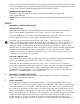
15 13 14 12 2 3 15 14 12. DDT LEDs The DDT LEDs will illuminate when signal compression is occurring in that channel. If you have a GPS 900 or 1500 and you have the DDT compression defeated, these LED will indicate the channel is clipping. 13. SIGNAL LEDs Each channel has a Signal LED, which comes on when the amplifier channel output exceeds 1 volt. 14. INPUT GAIN Each channel has an Input Gain control used to adjust the gain of the input signal.
LINE CORD For your safety, we have incorporated a removable 3-wire line (mains) cable with proper grounding facilities. It is not advisable to remove the ground contact under any circumstances. If it is necessary to use the equipment without proper grounding facilities, suitable grounding adapters should be used. Less noise and greatly reduced shock hazard exists when the unit is operated with the proper grounded receptacles. NOTE: Always turn off the amplifier before making audio connections.
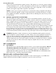
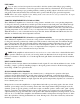
NOTE: Regardless of operating mode, NEVER connect amplifier outputs together! SPEAKER OUTPUT CONNECTIONS Speakers are connected using the output connectors on the rear of your amplifier. Make sure the amplifier is turned off before you change any output connections. Refer to the diagram on page 14 to view the wiring configuration of the Speakon connectors if your model utilizes them. Consult the Wire Gauge Chart on page 14 to find a suitable wire gauge and minimize losses of power in the speaker cables.
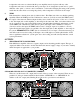
™ GPS Series Amplifiers Recommended Connection for Stereo Mode SP™ 7G GPS 900/1500 150VAC Units Only SP™ 7G NOTE: Minimum Load Impedance is 2 Ohms. To Additional Amplifier Input Channel B Input Source 1/4" jacks are wired in parallel with binding post. Tip = Positive Ring = Negative Channel A Input Source To Additional Amplifier Input DTH® 4215F All other GPS Models DTH® 4215F To Additional Amplifier Input NOTE: Minimum Load Impedance is 2 Ohms.
™ GPS Series Amplifiers Recommended Connection for Bridged Mode (-) To negative input terminal of speaker (+) GPS 900/1500 150VAC Units Only To positive input terminal of speaker NOTE: Minimum Load Impedance is 4 Ohms. Switch “in” for Bridge Mode To Additional Amplifier Input Input Source (-) To negative input terminal of speaker (+) All other GPS Models To positive input terminal of speaker NOTE: Minimum Load Impedance is 4 Ohms.
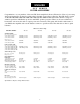
WIRE GAUGE CHART Cable Length (Feet) Stranded Wire Gauge (AWG) Power Loss Into 8 ohms Power Loss Into 4 ohms Power Loss Into 2 ohms 5' 18 AWG .79% 1.58% 3.16% 16 .05 1.0 2.0 14 .31 .62 1.24 12 .20 .40 .80 10 .125 .25 .50 18 AWG 1.58% 3.16% 6.32% 16 1.0 2.0 4.0 14 .62 1.25 2.50 12 .40 .80 1.6 10 .25 .50 1.0 18 AWG 8% 12.6% 25.2% 16 4.0 8.0 16.0 14 2.5 5.0 10 12 1.60 3.2 6.4 10 1.0 2.0 4.0 8 .625 1.25 2.50 16 AWG 8.0% 16.0% 32.
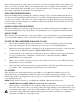
GPS™ 900 SPECIFICATIONS OUTPUT POWER: (Typical value) Stereo mode, both channels driven 2 ohms, 1 kHz, .1 THD 4 ohms, 1 kHz, .1 THD 8 ohms, 1 kHz, .1 THD - 450 WRMS per channel - 330 WRMS per channel - 200 WRMS per channel Bridge mode, mono 4 ohms, 1 kHz, .1 THD 8 ohms, 1 kHz, .1 THD - 900 WRMS - 660 WRMS RATED OUTPUT POWER: Stereo mode, both channels driven 4 ohms, 20 Hz to 20 kHz,0.03% THD 8 ohms, 20 Hz to 20 KHz,0.
GPS™ 1500 SPECIFICATIONS OUTPUT POWER: (Typical value) 2 ohms, 1 kHz, .1 THD 4 ohms, 1 kHz, .1 THD 8 ohms, 1 kHz, .1 THD Stereo mode, both channels driven - 750 WRMS per channel - 550 WRMS per channel - 320 WRMS per channel 4 ohms, 1 kHz, .1 THD 8 ohms, 1 kHz, .1 THD Bridge mode, mono - 1,500 WRMS - 1,100 WRMS RATED OUTPUT POWER: 4 ohms, 20 Hz to 20 kHz,0.03% THD 8 ohms, 20 Hz to 20 kHz,0.
GPS™ 2600 SPECIFICATIONS Rated Power (2 x 2 ohms) Rated Power (2 x 4 ohms) Rated Power (2 x 8 ohms) Rated Power (1 x 2 ohms) Rated Power (1 x 4 ohms) Rated Power (1 x 8 ohms) Minimum Load Impedance Maximum RMS Voltage Swing Frequency Response Power Bandwidth T.H.D. (2 x 2 ohms) T.H.D. (2 x 4 ohms) T.H.D.
GPS 3400 SPECIFICATIONS Rated Power (2 x 2 ohms): 1,700 watts @ 1 kHz both channels driven at <0.15% T.H.D. Rated Power (2 x 4 ohms): 1,200 watts @ 1 kHz both channels driven at <0.1% T.H.D. Rated Power (2 x 8 ohms): 750 watts @ 1 kHz both channels driven at <0.1% T.H.D. Rated Power (1 x 2 ohms): 1,800 watts @ 1 kHz at <0.1% T.H.D Rated Power (1 x 4 ohms): 1,350 watts @ 1 kHz at <0.1% T.H.D Rated Power (1 x 8 ohms): 825 watts @ 1 kHz at <0.05% T.H.D T.H.D. (2 x 2 ohms): <0.
GPS 3500 SPECIFICATIONS Rated Power (2 x 2 ohms): 1750 watts @ 1 kHz both channels driven at <0.15% T.H.D. Rated Power (2 x 4 ohms): 1200 watts @ 1 kHz both channels driven at <0.1% T.H.D. Rated Power (2 x 8 ohms): 775 watts @ 1 kHz both channels driven at <0.1% T.H.D. Rated Power (1 x 2 ohms): 1,850 watts @ 1 kHz at <0.1% T.H.D Rated Power (1 x 4 ohms): 1,350 watts @ 1 kHz at <0.1% T.H.D Rated Power (1 x 8 ohms): 850 watts @ 1 kHz at <0.05% T.H.
ESPAÑOL Serie GPS™ Amplificadores de Potencia Felicidades por tu compra del nuevo amplificador de potencia de la serie GPS de Peavey Electronics. Años de diseño y pruebas han producido una línea de amplificadores dinámicos completamente refinada. La serie GPS consiste de los modelos GPS 900, GPS 1500, GPS 2600, GPS 3400 y GPS 3500. Cada modelo incluye enfriamiento por túnel, ventiladores variables de dos velocidades, protección de iniciación y protección de bocinas DDT‘.
INSTALACIÓN Y MONTURAS La serie de amplificadores GPS usa dos espacios de rack, montables en un rack estándar de 19 pulgadas. En todos los amplificadores encontrarás cuatro agujeros para tornillos en la parte frontal. Busca las especificaciones de tu modelo en particular. COMIENZO RÁPIDO La siguiente sección abarca los pasos para el uso básico. Esto es sólo una guía de rápida referencia.
3. LED DE PODER (localizada en la parte frontal de la unidad. Ver diagrama en página 9) El LED de poder se iluminará cuando la unidad esté encendida (“ON”). PANEL TRASERO 1 4 6 7 5 8 LAS ENTRADAS Y SALIDAS DE SELECCIÓN DE MODO Una vez que le has dado poder de CA al amplificador, puedes conectar las entradas y salidas. Recuerda hacer esto cuando el poder está apagado (“OFF”), con el LED de poder no iluminado.
NOTA PARA GPS 900 y 1500 Cuando estos modelos son usados en modo ‘puente’, el LED de poder (3) para el canal B no se iluminará. NOTA: Refiérete a la sección de salidas para una explicación de cómo el interruptor de modo cambia las salidas a las bocinas. ENTRADAS 5. ENTRADA COMBINADA EN EL CANAL A GPS 900 y 1500 Estos modelos de la serie GPS ofrecen tanto entradas semi-balanceadas de 1/4" como XLR balanceadas por medio de los conectores “combo” de Neutrik® para ahorrar espacio.
línea de productos pasada y futura. Si esta unidad es utilizada en conjunto con otros productos competitivos que usen el sistema estándar IEC de polaridad, entonces el interruptor debe ser seleccionado a la posición abajo “in” (7), haciendo la aguja #2 positiva, aguja #3 negativa y aguja #1 tierra. Como con cualquier producto electrónico, la polaridad (fase) es importante, ya que la bocina que sea utilizada debe estar en fase con el resto de las bocinas y el sistema de amplificadores.
10 9 Todos los demás modelos GPS Estos modelos ofrecen conectores rápidos Speakon®. El Speakon® es un conector de cuatro cables marcados 1+, 1-, 2+ y 2-. Los conectores Speakon en tu amplificador GPS son las siguientes: agujas 1y 2- negativos en paralelo. Esto es típico para cada canal. NOTA: Consulta las especificaciones de tus bocinas para determinar la configuración del cableado que mejor funcione con tu sistema.
CONTROLES/INDICADORES DEL PANEL FRONTAL La siguiente sección describe los controles e indicadores que encontramos en la parte frontal de tu amplificador GPS. EL interruptor de poder y LED han sido explicados en una sección anterior, Poder de CA. 15 13 14 12 2 3 15 14 12. LEDS DE DDT Los LEDs del DDT se iluminarán cuando esté ocurriendo compresión en ese canal. SI tienes un GPS 900 ó 1500, y tienes la compresión apagada, los LEDs indicarán que el canal está saturando. 13.
operar es controlada por el corta circuitos del amplificador. Consulta las especificaciones para los requisitos que cada amplificador tiene. El poder que se aplique al amplificador debe ser consistente con las marcas e indicaciones en la parte trasera del amplificador. Los daños que se puedan crear por conectar el amplificador a una corriente equivocada no están cubiertos por ninguna garantía. CABLE DE PODER Para tu seguridad, hemos incorporado un cable removible de 3 cables (mains) propiamente aterrizado.
El modo puenteado convierte al amplificador en una unidad de un solo canal, con una total de potencia igual a la suma de los dos canales, con una carga el doble de aquella con uso independiente. En modo puenteado, los canales operan en polaridades opuestas para que un canal “empuje” y el otro “jale” al mismo tiempo. La señal es conectada al conector de entrada del canal A. Las bocinas son conectadas sólo a las terminales de salida designadas “+”.
CORTO CIRCUITO Si una salida sufre de un corto, el LFC‘, relay de circuito y circuitos térmicos automáticamente protegerán al amplificador. El circuito LFC‘ identifica el corto como una condición de ganancia irregular y reduce la ganancia de dicho canal a un nivel seguro. En condiciones severas o extremas, los relays de las bocinas desconectarán la carga e iniciarán una secuencia de encendido e inicialización.
WIRE GAUGE CHART Cable Length (Feet) Stranded Wire Gauge (AWG) Power Loss Into 8 ohms Power Loss Into 4 ohms Power Loss Into 2 ohms 5' 18 AWG .79% 1.58% 3.16% 16 .05 1.0 2.0 14 .31 .62 1.24 12 .20 .40 .80 10 .125 .25 .50 18 AWG 1.58% 3.16% 6.32% 16 1.0 2.0 4.0 14 .62 1.25 2.50 12 .40 .80 1.6 10 .25 .50 1.0 18 AWG 8% 12.6% 25.2% 16 4.0 8.0 16.0 14 2.5 5.0 10 12 1.60 3.2 6.4 10 1.0 2.0 4.0 8 .625 1.25 2.50 16 AWG 8.0% 16.0% 32.
ESPECIFICACIONES GPS™ 900 PODER DE SALIDA: (valor tipico) Modo estéreo, con los dos canales 2 ohmios, 1 kHz, 1% THD 8 ohmios, 1 kHz, 1% THD - 450 WRMS por canal - 200 WRMS por canal Modo puente, mono 4 ohmios, 1 kHz, 1% THD 8 ohmios, 1 kHz, 1% THD - 900 WRMS - 660 WRMS PODER DE SALIDA MEDIDO: Modo estéreo, con los dos canales 4 ohmios, 20 Hz a 20 kHz,0.03% THD 8 ohmios, 20 Hz a 20 KHz,0.
ESPECIFICACIONES GPS™ 1500 PODER DE SALIDA: (Tipico) Modo estéreo, con los dos canales 2 ohmios, 1 kHz, 1% THD 4 ohmios, 1 kHz, 1% THD 8 ohmios, 1 kHz, 1% THD - 750 WRMS Por canal - 550 WRMS por canal - 320 WRMS por canal Modo puente, mono 4 ohmios, 1 kHz, 1% THD 8 ohmios, 1 kHz, 1% THD - 1,500 WRMS - 1,100 WRMS PODER DE SALIDA MEDIDO: Modo estéreo, con los dos canales 4 ohmios, 20 Hz to 20 kHz,0.03% THD 8 ohmios, 20 Hz to 20 kHz,0.
ESPECIFICACIONES GPS™ 3500 Poder Medido (2 x 2 ohmios): Poder Medido (2 x 4 ohmios): Poder Medido (2 x 8 ohmios): Poder Medido (1 x 2 ohmios): Poder Medido (1 x 4 ohmios): Poder Medido (1 x 8 ohmios): Impedancia Mínima: Voltaje Máximo RMS: Respuesta de Frecuencias: Respuesta de potencia: T.H.D. (2 x 2 ohmios): T.H.D. (2 x 4 ohmios): T.H.D.
ESPECIFICACIONES GPS™ 2600 Poder Medido (2 x 2 ohmios) Poder Medido (2 x 4 ohmios) Poder Medido (2 x 8 ohmios) Poder Medido (1 x 2 ohmios) Poder Medido (1 x 4 ohmios) Poder Medido (1 x 8 ohmios) Impedancia Mínima Voltaje Máximo RMS Respuesta de Frecuencias Respuesta de potencia T.H.D. (2 x 2 ohmios) T.H.D. (2 x 4 ohmios) T.H.D.
ESPECIFICACIONES GPS™ 3400 Poder Medido (2 x 2 ohmios): Poder Medido (2 x 4 ohmios): Poder Medido (2 x 8 ohmios): Poder Medido (1 x 2 ohmios): Poder Medido (1 x 4 ohmios): Poder Medido (1 x 8 ohmios): T.H.D. (2 x 2 ohmios): T.H.D. (2 x 4 ohmios): T.H.D.
ESPECIFICACIONES GPS™ 3500 Poder Medido (2 x 2 ohmios): Poder Medido (2 x 4 ohmios): Poder Medido (2 x 8 ohmios): Poder Medido (1 x 2 ohmios): Poder Medido (1 x 4 ohmios): Poder Medido (1 x 8 ohmios): Impedancia Mínima: Voltaje Máximo RMS: Respuesta de Frecuencias: Respuesta de potencia: T.H.D. (2 x 2 ohmios): T.H.D. (2 x 4 ohmios): T.H.D.
FRANÇAIS Série GPS™ Amplificateurs de puissance Nous vous félicitons pour votre achat du nouvel amplificateur de la Série GPS de Peavey Electronics. Des années d'expérience dans la conception et l’essai d’amplis nous ont permis de mettre au point une ligne d'amplis raffinés et dynamiques. La Série GPS se compose des modèles GPS 900, GPS 1500, GPS 2600, GPS 3400 et GPS 3500.
uniquement l’emballage d’usine original. Remplissez maintenant votre carte d’enregistrement. Il est important de remplir le formulaire complet et de l'envoyer à Peavey Electronics pour pouvoir bénéficier de votre garantie. INSTALLATION ET MONTAGE Les amplificateurs de la Série GPS sont des unités occupant 2 racks (emplacements “porte-ampli”), montées dans un rack standard de 48 cm. Tous les amplificateurs disposent de quatre orifices de montage sur le panneau avant.
2. COMMUTATEUR D’ALIMENTATION C.A. (situé à l’avant de l’unité). (Voir diagramme page 9). Un commutateur d’alimentation à deux positions se trouve sur le côté droit du panneau avant. L’amplificateur est sous tension (“ON”) lorsqu’on a appuyé sur la partie supérieure du commutateur pour la mettre sur “IN”. L’amplificateur est hors tension (“OFF”) lorsqu’on a appuyé sur la partie inférieure du commutateur pour la mettre sur “IN”. 3. VOYANT DEL D’ALIMENTATION (situé à l’avant de l’unité).
PONTÉ OU MONO: En mode “ponté”, les deux canaux de l’amplificateur se combinent pour former un seul canal mono. Ce mode offre l’avantage de doubler la puissance de votre amplificateur. Reportez-vous aux spécifications de ce manuel pour plus de détails sur la puissance de sortie de votre modèle. Pour utiliser les amplis de la Série GPS en monde “ponté”, placez le Commutateur de Mode sur “in”, c’est-à-dire vers le bas. L’ampli est maintenant un ampli mono et ne nécessite plus qu’une seule entrée.
7. POLARITÉ D’ENTRÉE Vous trouverez, entre les entrées du Canal A et celles du Canal B, un commutateur de Polarité d’entrée encastré (7) qui permet à l’utilisateur de sélectionner la polarité (phase) souhaitée des entrées XLR. Ce commutateur est de type push-push (‘pousse-pousse’), et un “outil” de petit diamètre est nécessaire pour sélectionner la position souhaitée.
Modèles GPS 900 ou GPS 1500 120 VAC (domestique): Ces deux modèles possèdent des prises de sortie de 6,3 mm situées dans la partie supérieure centrale du panneau arrière. Il y a deux prises parallèles de 6,3 mm par canal qui portent l’étiquette “CANAL A” ou “CANAL B”). Outre les prises de sortie de 6,3 mm, les bornes de raccordement (10) sont également fournies pour chaque canal . 10 9 Tous les autres modèles GPS: Ces modèles disposent de doubles connecteurs Speakon® Quick.
COMPRESSION DDT 11. DESACTIVATION DDT Ce commutateur sert à désactiver la compression DDT utilisée pour éviter la saturation du signal. Seuls les modèles GPS 900 et 1500 disposent de cette fonction. Il est recommandé de laisser la compression DDT activée à tout moment pour protéger les haut-parleurs des ondes de type carré néfastes. Pour activer la fonction DDT, appuyez sur le commutateur pour le mettre sur “in”.
fonctionnement et la vitesse des ventilateurs dépendent de la température et changent à mesure que les dissipateurs de chaleur de l’amplificateur ont besoin d’être refroidis. (Voir Remarques relatives au fonctionnement). Ne pas bloquer cet orifice d’échappement! Durant son fonctionnement, votre amplificateur de la Série GPS nécessitera de l’air frais pour permettre au tube de refroidissement de fonctionner correctement.
CONNEXIONS D’ENTRÉE Le connecteur d’entrée accepte les signaux audio balancés et non balancés. Dans le cas d’une utilisation avec une source non balancée, reliez l’entrée inversée (-) à la terre en installant un câble de raccordement vers la mise à la terre du signal. Si l’entrée inversée est laissée flottante, il en résultera une perte de gain de 6 dB.
permettre à l’amplificateur de fonctionner en toute sécurité à une charge anormale. Une activation modérée du LFC est imperceptible lors d’une utilisation normale. De plus, en cas d’impédance extrêmement basse ou de court-circuit lors de transmissions où le niveau du signal est élevé, le relais de sortie de l'amplificateur s’ouvrira. INITIALIZATION PROTECTION™ (IP™) (PROTECTION D’INITIALISATION) L’IP™ fonctionne lorsque l’amplificateur est sous tension, ou après une condition de protection.
WIRE GAUGE CHART Cable Length (Feet) Stranded Wire Gauge (AWG) Power Loss Into 8 ohms Power Loss Into 4 ohms Power Loss Into 2 ohms 5' 18 AWG .79% 1.58% 3.16% 16 .05 1.0 2.0 14 .31 .62 1.24 12 .20 .40 .80 10 .125 .25 .50 18 AWG 1.58% 3.16% 6.32% 16 1.0 2.0 4.0 14 .62 1.25 2.50 12 .40 .80 1.6 10 .25 .50 1.0 18 AWG 8% 12.6% 25.2% 16 4.0 8.0 16.0 14 2.5 5.0 10 12 1.60 3.2 6.4 10 1.0 2.0 4.0 8 .625 1.25 2.50 16 AWG 8.0% 16.0% 32.
SPECIFICATIONS DU GPS™ 900 PUISSANCE DE SORTIE: (Valeur caractéristique) Mode stéréo, les deux canaux en fonction 2 ohms, 1 kHz, 1% THD 4 ohms, 1 kHz, 1% THD 8 ohms, 1 kHz, 1% THD - 450 WRMS par canal - 330 WRMS par canal - 200 WRMS par canal Mode 'ponté', mono 4 ohms, 1 kHz, 1% THD 8 ohms, 1 kHz, 1% THD PUISSANCE NOMINALE DE SORTIE: - 900 WRMS - 660 WRMS Mode stéréo, les deux canaux en fonction 4 ohms, 20 Hz à 20 kHz, 0,03% THD 8 ohms, 20 Hz à 20 kHz, 0,02% THD - 300 WRMS par canal - 170 WRMS par
SPECIFICATIONS DU GPS™ 1500 PUISSANCE DE SORTIE: (Valeur caractéristique) Mode stéréo, les deux canaux en fonction 2 ohms, 1 kHz, 1% THD 4 ohms, 1 kHz, 1% THD 8 ohms, 1 kHz, 1% THD - 750 WRMS par canal - 550 WRMS par canal - 320 WRMS par canal Mode 'ponté', mono 4 ohms, 1 kHz, 1% THD 8 ohms, 1 kHz, 1% THD PUISSANCE NOMINALE DE SORTIE: - 1.500 WRMS - 1.
SPECIFICATIONS DU GPS™ 3500 Puissance nominale (2 x 2 ohms): Puissance nominale (2 x 4 ohms): Puissance nominale (2 x 8 ohms): Puissance nominale (1 x 2 ohms): Puissance nominale (1 x 4 ohms): Puissance nominale (1 x 8 ohms): Impédance minimale de charge: Ecart maximum de tension RMS: Réponse de fréquence: Bande passante: T.H.D. (2 x 2 ohms): T.H.D. (2 x 4 ohms): T.H.D.
SPECIFICATIONS DU GPS™ 2600 Puissance nominale (2 x 2 ohms) Puissance nominale (2 x 4 ohms) Puissance nominale (2 x 8 ohms) Puissance nominale (1 x 2 ohms) Puissance nominale (1 x 4 ohms) Puissance nominale (1 x 8 ohms) Impédance minimale de charge Ecart maximum de tension RMS Réponse de fréquence Bande passante T.H.D. (2 x 2 ohms) T.H.D. (4 x 2 ohms) T.H.D.
SPECIFICATIONS DU GPS™ 3400 Puissance nominale (2 x 2 ohms): Puissance nominale (2 x 4 ohms): Puissance nominale (2 x 8 ohms): Puissance nominale (1 x 2 ohms): Puissance nominale (1 x 4 ohms): Puissance nominale (1 x 8 ohms): T.H.D. (2 x 2 ohms): T.H.D. (2 x 4 ohms): T.H.D.
SPECIFICATIONS DU GPS™ 3500 Puissance nominale (2 x 2 ohms): Puissance nominale (2 x 4 ohms): Puissance nominale (2 x 8 ohms): Puissance nominale (1 x 2 ohms): Puissance nominale (1 x 4 ohms): Puissance nominale (1 x 8 ohms): Impédance minimale de charge: Ecart maximum de tension RMS: Réponse de fréquence: Bande passante: T.H.D. (2 x 2 ohms): T.H.D. (2 x 4 ohms): T.H.D.
DEUTSCH GPS™ Series Endstufen Herzlichen Glückwunsch zum Kauf eines neuen GPS Series-Verstärkers von Peavey Electronics. Jahrelange Entwicklungen und Testverfahren haben eine vollkommen überarbeitete, dynamische Endstufen-Produktlinie hervorgebracht. Die GPS-Serie besteht aus dem GPS 900, GPS 1500, GPS 2600, GPS 3400 und dem GPS 3500. Jedes Modell zeichnet sich durch Tunnel-Kühlung, zwei Lüfter mit variabler Geschwindigkeit, einen Initialisierungsschutz und eine DDT™-Lautsprecherschutzfunktion aus.
Verpackungsmaterialien auf. Falls Sie einmal das Gerät zurück an Peavey Electronics, eines der ServiceCenter oder den Händler schicken müssen, benötigen Sie die Originalverpackung. Bitte füllen Sie jetzt die Registrierungskarte aus. Für Ihren Garantieanspruch ist es wichtig, dass Sie alle geforderten Angaben eintragen und dann an Peavey Electronics senden. INSTALLATION UND EINBAU GPS Series-Verstärker sind Rack-Geräte mit 2 HE, die in ein Standard 19-Zoll-Rack eingebaut werden können.
2. AC POWER-SCHALTER (an der Vorderseite des Gerätes. Siehe Abbildung auf Seite 9) Sie finden einen Netzschalter mit zwei Stellungen auf der rechten Seite des vorderen Bedienfeldes. Drücken Sie die obere Position “IN” und der Verstärker ist eingeschaltet. In der unteren Position “OFF” schalten Sie das Gerät aus. 3. POWER LED-ANZEIGE (auf der Vorderseite des Gerätes. SieheAbbildung auf Seite 9) Die aufleuchtende Power LED-Anzeige gibt an, dass der Verstärker eingeschaltet ist.
Bridged oder Mono: In dem “Bridge”-Modus sind beide Kanäle miteinander zu einem Mono-Kanal gekoppelt. Der Vorteil liegt darin, dass sich die Ausgangsleistung verdoppelt. Lesen Sie die detaillierten Spezifikationen zur Ausgangsleistung für Ihr Modell in dieser Gebrauchsanleitung nach. Setzen Sie den Mode-Schalter auf die “In”-Position und Ihr GPS Series-Verstärker arbeitet in dem “Bridge”-Modus. Das Gerät ist jetzt ein Mono-Verstärker und braucht nur einen einzigen Eingang.
7. Input-Polung Zwischen dem Kanal A- und dem Kanal B-Eingang finden Sie einen eingebauten InputPolungsschalter (7), der es Ihnen ermöglicht, die gewünschte Polung (Phase) des XLR-Eingangs auszuwählen. Dieser Schalter ist ein Drucktastenschalter und Sie benötigen ein Werkzeug (z.B. kleiner Schraubenzieher), um die gewünschte Position einzustellen. Die Polung in der “Out”-Position (voreingestellt) ist: Pin 3 = Plus, Pin 2 = Minus und Pin 1= Masse. Viele Peavey-Verstärker sind auf diese Weise gepolt.
GPS 900 oder GPS 1500 120 VAC (USA) Modelle: Diese beiden Modelle haben eine 6,3 mm Klinken-Ausgangsbuchse im oberen Bereich des rückwärtigen Bedienfeldes. Es gibt zwei parallele 6,3 mm Klinke-Buchsen pro Kanal, die entweder “CHANNEL A” oder “CHANNEL B” heißen. Zusätzlich finden Sie für jeden Kanal Anschlussklemmen (10). 10 9 Alle anderen GPS-Modelle: An diesen Modellen sind Dual-Speakon® Quick-Ausgänge angebracht. Die Speakon® ist ein vierpoliger Ausgang mit folgender Polung: 1+, 1-, 2+ und 2-.
DDT-Compression 11. DDT-Unterdrückung Mit diesem Schalter unterdrücken Sie die DDT-Compression, die vor Pegelspitzen schützt. Nur die Modelle GPS 900 und 1500 bieten diese Funktion an. Es wird empfohlen, die Funktion immer aktiviert zu lassen, um Ihre Lautsprecher vor schädlichen Rechteckwellen zu schützen. Die DDT-Funktion wird deaktiviert, wenn Sie den Schalter in die “In”-Position drücken. Wird eine DDT-Compression in dem jeweiligen Kanal wirksam, leuchten die DDT LED-Anzeigen (12) auf.
Geschwindigkeit der Lüfter hängen von der Temperatur ab. Die Geschwindigkeit ändert sich mit dem verstärkten Bedarf an Kühlung. (Lesen Sie hierzu den Abschnitt “Anmerkungen zum Betrieb”.) Halten Sie die Öffnungen zu den Lüftern frei! Während des Betriebs muss Ihr Verstärker, um korrekt zu funktionieren, frische Luft für die Kühlung aufnehmen. Werden diese Öffnungen an Vorderund Rückseite nicht freigehalten, kann sich Ihr Verstärker abschalten.
EINGANGSANSCHLÜSSE Der Eingangs-Anschluss akzeptiert symmetrische und asymmetrische Audiosignale. Falls Sie eine asymmetrische Quelle benutzen, sollten Sie den Minus-Pol an Masse legen, indem Sie einen Jumper auf Signal zu Masse setzen. Wenn der Minus-Pol nicht geerdet wird, verlieren Sie 6 dB an Gain. BETRIEBSARTEN GPS Series-Verstärker sind an den Eingangsanschlüssen und dem Mode-Schalter für den Zwei-Kanal- (Stereo) oder den “Bridged”-Modus konfiguriert.
Initialization-Protection™ (IP™) IP™ ist immer dann aktiviert, wenn der Verstärker angeschaltet wird oder gerade eine Schutzfunktion ausgeübt wurde. Angeschaltet geht der Verstärker in den Schutzmodus und trennt die Lautsprecher von der Signallast, bis der Verstärker anzeigt, dass die Betriebsbedingungen sich wieder normalisiert haben. Der IP™-Schaltkreis dämpft das Signal während des Einschaltens oder wenn eine Schutzfunktion aktiviert ist.
WIRE GAUGE CHART Cable Length (Feet) Stranded Wire Gauge (AWG) Power Loss Into 8 ohms Power Loss Into 4 ohms Power Loss Into 2 ohms 5' 18 AWG .79% 1.58% 3.16% 16 .05 1.0 2.0 14 .31 .62 1.24 12 .20 .40 .80 10 .125 .25 .50 18 AWG 1.58% 3.16% 6.32% 16 1.0 2.0 4.0 14 .62 1.25 2.50 12 .40 .80 1.6 10 .25 .50 1.0 18 AWG 8% 12.6% 25.2% 16 4.0 8.0 16.0 14 2.5 5.0 10 12 1.60 3.2 6.4 10 1.0 2.0 4.0 8 .625 1.25 2.50 16 AWG 8.0% 16.0% 32.
GPS™ 900 SPEZIFIKATIONEN AUSGANGSNENNLEISTUNG: (Standardwert) Stereomodus, beide Kanäle in Betrieb 2 Ohm, 1 kHz, 1% THD 4 Ohm, 1 kHz, 1% THD 8 Ohm, 1 kHz, 1% THD - 450 WRMS pro Kanal - 330 WRMS pro Kanal - 200 WRMS pro Kanal Bridge-Modus, Mono 4 Ohm, 1 kHz, 1% THD 8 Ohm, 1 kHz, 1% THD - 900 WRMS - 660 WRMS AUSGANGSNENNLEISTUNG: Stereomodus, beide Kanäle in Betrieb 4 Ohm, 20 Hz bis 20kHz, 0,03% THD 8 Ohm, 20 Hz bis 20kHz, 0,02% THD - 300 WRMS pro Kanal - 170 WRMS pro Kanal ANSTIEGSGESCHWINDIGKEIT:(
GPS™ 1500 SPEZIFIKATIONEN AUSGANGSNENNLEISTUNG: (Standardwert) Stereomodus, beide Kanäle in Betrieb 2 Ohm, 1 kHz, 1% THD 4 Ohm, 1 kHz, 1% THD 8 Ohm, 1 kHz, 1% THD - 750 WRMS pro Kanal - 550 WRMS pro Kanal - 320 WRMS pro Kanal Bridge-Modus, Mono 4 Ohm, 1 kHz, 1% THD 8 Ohm, 1 kHz, 1% THD - 1,500 WRMS - 1,100 WRMS AUSGANGSNENNLEISTUNG: Stereomodus, beide Kanäle in Betrieb 4 Ohm, 20 Hz bis 20 kHz, 0,03% THD 8 Ohm, 20 Hz bis 20 kHz, 0,02% THD - 500 WRMS pro Kanal - 280 WRMS pro Kanal ANSTIEGSGESCHWINDI
GPS™ 3500 SPEZIFIKATIONEN Nennleistung (2 x 2 Ohm): Nennleistung (2 x 4 Ohm): Nennleistung (2 x 8 Ohm): Nennleistung (1 x 2 Ohm): Nennleistung (1 x 4 Ohm): Nennleistung (1 x 8 Ohm): Minimale Belastungsimpedanz: Maximaler RMS Spannungshub: Frequenzgang: Leistungsbandbreite: T.H.D. (2 x 2 Ohm): T.H.D. (2 x 4 Ohm): T.H.D.
GPS™ 2600 SPEZIFIKATIONEN Nennleistung (2 x 2 Ohm) Nennleistung (2 x 4 Ohm) Nennleistung (2 x 8 Ohm) Nennleistung (1 x 2 Ohm) Nennleistung (1 x 4 Ohm) Nennleistung (1 x 8 Ohm) Minimale Belastungsimpedanz Maximaler RMS Spannungshub Frequenzgang Leistungsbandbreite T.H.D. (2 x 2 Ohm) T.H.D. (2 x 4 Ohm) T.H.D.
GPS™ 3400 SPEZIFIKATIONEN Nennleistung (2 x 2 Ohm): Nennleistung (2 x 4 Ohm): Nennleistung (2 x 8 Ohm): Nennleistung (1 x 2 Ohm): Nennleistung (1 x 4 Ohm): Nennleistung (1 x 8 Ohm): T.H.D. (2 x 2 Ohm): T.H.D. (2 x 4 Ohm): T.H.D.
GPS™ 3500 SPEZIFIKATIONEN Nennleistung (2 x 2 Ohm): Nennleistung (2 x 4 Ohm): Nennleistung (2 x 8 Ohm): Nennleistung (1 x 2 Ohm): Nennleistung (1 x 4 Ohm): Nennleistung (1 x 8 Ohm): Minimale Belastungsimpedanz: Maximaler RMS Spannungshub: Frequenzgang: Leistungsbandbreite: T.H.D. (2 x 2 Ohm): T.H.D. (2 x 4 Ohm): T.H.D.
PEAVEY ELECTRONICS CORPORATION LIMITED WARRANTY Effective Date: July 1, 1998 What This Warranty Covers Your Peavey Warranty covers defects in material and workmanship in Peavey products purchased and serviced in the U.S.A. and Canada.
IMPORTANT SAFETY INSTRUCTIONS WARNING: When using electric products, basic cautions should always be followed, including the following: 1. Read these instructions. 2. Keep these instructions. 3. Heed all warnings. 4. Follow all instructions. 5. Do not use this apparatus near water. For example, near or in a bathtub, swimming pool, sink, wet basement, etc. 6. Clean only with a damp cloth. 7. Do not block any of the ventilation openings. Install in accordance with manufacturer’s instructions.