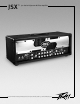
JSX ™ Joe Satriani Signature All-Tube Amplifier For more information on other great Peavey products, visit your local Peavey dealer or go online at www.peavey.
Intended to alert the user to the presence of uninsulated “dangerous voltage” within the product’s enclosure that may be of sufficient magnitude to constitute a risk of electric shock to persons. Intended to alert the user of the presence of important operating and maintenance (servicing) instructions in the literature accompanying the product. CAUTION: Risk of electrical shock — DO NOT OPEN! CAUTION: To reduce the risk of electric shock, do not remove cover. No user serviceable parts inside.
IMPORTANT SAFETY INSTRUCTIONS WARNING: When using electrical products, basic cautions should always be followed, including the following: 1. 2. 3. 4. 5. 6. 7. 8. 9. 10. 11. 12. 13. 14. 15. 16. 17. 18. Read these instructions. Keep these instructions. Heed all warnings. Follow all instructions. Do not use this apparatus near water. Clean only with a dry cloth. Do not block any of the ventilation openings. Install in accordance with manufacturer’s instructions.
ENGLISH ™ Congratulations on purchasing a Peavey JSX guitar amplifier. The JSX is a guitar player’s dream come true, an amp that delivers superior sound quality and high performance for any style of guitar playing. Only the finest materials are used to create this great-sounding, rugged, tour-worthy and very unique-looking tone machine.
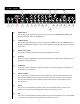
F R O N T PA N E L 4 1 2 3 5 13 6 7 8 10 9 11 14 15 20 16 17 10 18 19 12 (1) POWER SWITCH This two-way toggle switch applies mains power to the unit. The red POWER STATUS LAMP (3) will illuminate when this switch is in the ON position. (2) STANDBY SWITCH This two-way toggle switch allows the amp to be placed in STANDBY mode. In the STANDBY position the tubes stay hot but the amplifier is not operational. Switching to the ON position places the amp in active mode.
(9) BASS This control, on both the Ultra and Crunch channels, varies the low frequency response of the amplifier. It is an active control (shelving type) and allows ˜12 dB of boost or cut. (10) VOLUME This control, on all three channels, sets the overall level of its respective channel. (11) GAIN This control, on both the Ultra and Crunch channels, controls the input volume level of the channel. Rotating this control clockwise will increase the amount of preamp distortion and sustain.
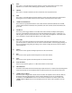
R E A R PA N E L 31 22 21 24 23 (21) 28 26 25 30 29 27 32 33 EFFECTS SEND LEVEL This calibrated (0 – 10) control sets the level of signal being sent to external effects and/or signal processors. Clockwise rotation increases the amount of signal being sent; counterclockwise rotation decreases the amount. For the quietest operation, the EFFECTS SEND LEVEL should be set as high as possible. Generally, the SEND and RETURN levels should be set oppositely.
(27) CABINET IMPEDANCE SWITCH This three-position switch allows appropriate selection of speaker cabinet impedance. If two enclosures of equal impedance are used, the switch should be set to half the individual value. For example, two 16 Ohm enclosures necessitate an 8 Ohm setting, while two 8 Ohm enclosures would require a 4 Ohm setting. Minimum speaker impedance is 4 Ohms. (28) SPEAKER OUTPUTS These paralleled 1/4" mono (TS) jacks are provided for the connection of speaker enclosure(s).
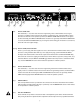
F O OTS W I TC H 34 35 36 37 (34) CABLE CONNECTOR This seven-pin DIN connector is provided for connecting the footswitch to the amplifier REMOTE SWITCH (25) via the cable included in the carton. Connections at the switch and the amplifier should be made before the amp is powered up. (35) ULTRA/CRUNCH SELECTOR This switch selects between the Ultra and Crunch channels on the amplifier. The adjacent LED will illuminate when the Ultra channel is selected.
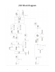
JSX™ Block Diagram 10
JSX ™ SPECIFICATIONS POWER AMPLIFIER SECTION: Tubes: Four EL34 tubes with 12AX7 driver Clean Channel: Remote Footswitch: Nominal Input Level: -10 dBV, 300 mV RMS Minimum Input Level: -22 dBV, 80 mV RMS Maximum Input Level: 0 dBV, 1 .
ESPAÑOL ™ Felicitaciones en la compra de su amplificador para guitarra Peavey JSX. El JSX es para el guitarrista su sueño hecho realidad – el amplificador que le impartirá tanto a su sonido como a cualquiera que sea su estilo de ejecución, una calidad superior. Sólo los materiales más finos se han utilizado en crear esta máquina tonal de gran sonido, resistente, digna de giras, y con una apariencia única.
PA N E L F R O N TA L 4 1 2 3 5 13 6 7 8 10 9 11 14 15 20 16 17 10 18 19 12 (1) INTERRUPTOR DE POTENCIA Este interruptor de dos posiciones aplica corriente a la unidad. La lámpara de estatus roja (3) se iluminará cuando el interruptor de encuentre en la posición de encendido (ON). (2) INTERRUPTOR DE STANDBY Este interruptor de dos posiciones permite poner al amplificador en modo STANDBY.
9) GRAVES Este control, tanto en el canal Crunch como en el Ultra, varia la respuesta de frecuencias graves del amplificador. Es un control activo y permite ˜12 dB de recorte o aumento. (10) VOLUMEN Este control, en los tres canales, ajusta el nivel de su respectivo canal. (11) GANANCIA Este control, tanto en el canal Ultra como Crunch, controla el volumen de entrada del canal. El rotar la perilla en dirección de las manecillas del reloj incrementará la cantidad de distorsión y suspensión.
PA N E L T R A S E R O 31 22 21 24 23 (21) 28 26 25 30 29 27 32 33 NIVEL DE ENVIO DE EFECTOS Este control calibrado (0-10) ajusta el nivel de señal que se manda a una unidad externa de efectos o procesador. La rotación en dirección de las manecillas del reloj incrementa la cantidad de señal que se manda, contrarreloj la reduce. Para la operación más silenciosa el NIVEL DE ENVIO DE EFECTOS debe estar lo más alto posible. Generalmente, los niveles de ENVIO y RETORNO deben ser ajustados opuestamente.
(27) INTERRUPTOR DE IMPEDANCIA IMPEDANCIA Este interruptor de tres posiciones permite seleccionar la impedancia del gabinete de altavoces. Si se usan dos gabinetes de distintas impedancias, el interruptor debe estar en la mitad de su valor individual. Por ejemplo, dos altavoces de 16 ohmios necesitan una posición de 8 ohmios, mientras que dos altavoces de 8 ohmios necesitan la posición de 4 ohmios. La impedancia mínima en altavoces es 4 ohmios.
PEDAL 34 35 36 37 (30) CONECTOR DE CABLE Este conector tipo DIN de 7 agujas se provee para conectar una pedalera en el CONTROL REMOTO (25) vía el cable incluido en el paquete. Las conexiones de la pedalera y amplificador deben llevarse a cabo antes de encenderlo. (31) SELECTOR ULTRA / CRUNCH Este interruptor selecciona entre los canales Ultra y Crunch del amplificador. El LED adyacente se iluminará cuando el canal es seleccionado. Cuando el LED no esté encendido, el canal Crunch está seleccionado.
JSX™ Diagrama en Bloque 18
JSX ™ ESPECIFICACIONES POWER AMPLIFIER SECTION: Bulbos: Cuatro tubos EL34 con 12AX7 impulsor Potencia Nominal & Carga: 120 Wats (Vatios) RMS a 16, 8, ó 4 Ohmios Capacidad @ Clipping: Potencial @ Mutilación de Señales (típicamente @ 5% THD, 1 kHz, línea 120 VAC ) 120 Wats (Vatios) RMS a 16, 8, ó 4 Ohmios Respuesta de frecuencias: +/- 3 dB, 50 Hz a 20 kHz @ 90 Wats (Vatios) RMS a 8 Ohmios Hum y ruido: Mayor de 76 dB bajo potencia nominal Consumo de Potencia: Doméstico: 400 Wats (Vatios), 50/60 Hz, 120
FRANÇAIS ™ Nous vous félicitons d’avoir fait l’acquisition d’un amplificateur guitare Peavey JSX . Le JSX est le rêve d’un guitariste devenu réalité, un ampli qui fournit une qualité sonore supérieure et une haute performance quel que soit le jeu de guitare. Seuls les matériaux les plus nobles ont été utilisés pour créer cette machine solide, digne de tournées, au son incroyable et au look unique.
F R O N T PA N E L 4 1 2 3 5 13 6 7 8 10 9 11 14 15 20 16 17 10 18 19 12 (1) SELECTEUR D’ALIMENTATION Cet interrupteur 2-positions contrôle l’alimentation électrique pour votre unité. Une lampe de statut (3) s’illumine lorsque l’unité est sous tension. 2) SELECTEUR DE CIRCUIT DE CHAUFFE (STANDBY) Cet interrupteur 2-positions permet à votre unité d’alimenter les lampes sans les rendre opérationnelles (aucun signal en sortie).
(9) BASSES Ce contrôle, sur les canaux Ultra et Crunch, permet de modifier la réponse en basses fréquences de votre unité sur ces canaux. Ce contrôle est actif et vous permet jusqu’à ˜12 dB de modification (boost ou cut). (10) VOLUME Ce contrôle, sur chacun des canaux, permet de régler le niveau du canal concerné. (11) GAIN Ce contrôle, sur les canaux Ultra et Crunch, vous permet de déterminer le niveau du signal d’entrée dans le canal correspondant.
R E A R PA N E L 31 22 21 24 23 (21) 28 26 25 30 29 27 32 33 CONTROLE DE NIVEAU D’ENVOI D’EFFETS (EFFECTS SEND LEVEL) Ce contrôle calibré (0 –10) détermine le niveau du signal envoyé par la sortie EFFECTS SEND(24) à une unité externe d’effets ou autre (Pédale de volume,...). Le tourner horairement augmentera ce niveau et vice-versa. Sa position est déterminée par la sensibilité de l’unité externe en question.
(28) SORTIES HAUTS-PARLEURS Ces jack 1/4" mono (TS) sont montés en parallèles et vous permettent de connecter vos enceintes à votre unité. Le sélecteur d’impédance (27) doit ëtre positionné sur la position donnée par le nombre et l’impédance des enceintes que vous comptez utiliser. La charge de travail minimum de votre unité est 4 Ohms (29) CONTROLE DE SORTIE LIGNE (LINE LEVEL) Ce potentiomètre permet de controler le niveau du signal à la sortie ligne de votre unité (30).
F O OTS W I TC H 34 35 36 37 (34) CONNECTEUR CABLE DIN Ce connecteurs 7-pins DIN vous permet de connecter le pédalier à votre unité via un cable 7-pins DIN (fourni). Le branchement du pédalier doit se faire avant la mise sous tension de votre unité. (35) SELECTEUR ULTRA / CRUNCH Ce sélecteur vous permet de choisir entre les canaux Ultra et Crunch de votre unité. La Led correspondante s’illuminera quand le canal Ultra est actif, et restera éteinte pour indiquer la sélection du canal Crunch.
JSX™ Block Diagram 26
JSX ™ SPECIFICATIONS SECTION AMPLIFICATEUR DE PUISSANCE Lampes: Quatre lampes EL34 combinées à des 12AX7 Puissance Nominale et Charge: 120 Watts RMS sous16, 8 ou 4 Ohms. Puissance en crête: (typiquement à 5% THD, 1 kHz, 120 V en courant alternatif ) 120 Watts RMS sous 16, 8 ou 4 Ohms. Réponse en fréquence: +/- 3 dB, de 50 Hz à 20 kHz à 90 Watts RMS sous 8 Ohms. Ronflement et Bruit: Supérieur à 76 dB en dessous de la puissance nominale.
DEUTSCH ™ Herzlichen Glückwunsch! Sie haben gerade einen Peavey JSX Gitarrenverstärker erworben. Mit dem JSX wird ein Gitarristentraum wahr, denn der Verstärker liefert hervorragende Soundqualität und viel Leistung für jede Art von Gitarrenspiel. Für den Bau dieses robusten Verstärkers, der sich durch tollen Klang und ein einzigartiges Design auszeichnet und der jede Tour problemlos mitmacht, wurden nur die besten Materialien verwendet.
F R O N T P L AT T E 4 1 2 3 5 13 6 7 8 10 9 11 14 15 20 16 17 10 18 19 12 ((1) POWER Mit diesem Knebelschalter schalten Sie den Strom für das Gerät ein oder aus. In der Schalterstellung ON leuchtet die rote Statusanzeige (3). (2) STANDBY Mit diesem Knebelschalter schalten Sie den Verstärker in den STANDBY-Betrieb, d.h. die Betriebstemperatur der Röhren bleibt erhalten, der Verstärker als solches ist jedoch inaktiv.
(9) BASS Mit diesem Regler stellen Sie in den Kanälen Ultra und Crunch den Bassanteil ein (aktiver ShelvingRegler für bis zu ˜12 dB Anhebung oder Absenkung). (10) VOLUME Mit diesem Regler bestimmen Sie in allen drei Kanälen die Lautstärke des jeweiligen Verstärkerkanals. (11) GAIN Mit diesem Regler bestimmen Sie den Eingangspegel für die Kanäle Ultra und Crunch. Mit dem Uhrzeigersinn gedreht erhöhen Sie den Verzerrungsgrad des Vorverstärkers und damit das Sustain.
RÜCKSEITE 31 22 21 24 23 (21) 28 26 25 30 29 27 32 33 EFFECTS SEND-REGLER Mit diesem kalibrierten Trimregler (0 –10) stellen Sie den an ein externes Effektgerät oder anderen Signalprozessor ausgegebenen Pegel ein. Mit dem Uhrzeigersinn gedreht erhöht sich der Signalanteil, gegen den Uhrzeigersinn gedreht verringert er sich. Für ein möglichst rauschfreies Signal empfiehlt sich eine hohe Einstellung des EFFECTS SEND-Pegels.
(27) CABINET IMPEDANCE Mit diesem Dreifach-Schalter stellen Sie die Lautsprecherimpedanz ein. Bei Anschluss zweier Lautsprecherboxen mit identischen Impedanzwerten setzen Sie diesen Schalter auf den halben Wert einer Box. Bei zwei 16-Ohm-Boxen stellen Sie den Impedanzwahlschalter also auf 8 Ohm ein, bei zwei 8-Ohm-Boxen auf 4 Ohm (Mindestimpedanz 4 Ohm).
F U S S S C H A LT E R 34 35 36 37 (34) REMOTE CABLE An diese 7-polige DIN-Buchse schließen Sie das im Lieferumfang enthaltene FußschalterAnschlusskabel an und verbinden es mit dem Fußschaltereingang des Verstärkers (REMOTE SWITCH, 25). Beachten Sie, dass die Kabelverbindung bei Einschalten des Verstärkers bereits bestehen sollte.
JSX™ Block Diagram 34
JSX ™ TECHNISCHE DATEN ENDSTUFE: Röhren: Vier EL34-Röhren mit 12AX7-Treiber Clean-Kanal: Fußschalter: Nenneingangspegel: -10 dBV, 300 mV RMS Mindesteingangspegel: -22 dBV, 80 mV RMS Höchsteingangspegel: 0 dBV, 1 mV RMS Spezieller Dreitasten-Fußschalter aus Metall mit LED-Anzeigen und abziehbarem Kabel (beiliegend) zur Auswahl der drei Kanäle und Deaktivierung der Effektschleife.
Features and specifications subject to change without notice. Peavey Electronics Corporation • 711 A Street • Meridian • MS • 39301 (601) 483-5365 • FAX (601) 486-1278 • www.peavey.com ©2004 80304994 Printed in the U.S.A.