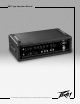
MAX® 450 Operation Manual For more information on other great Peavey products, go to your local Peavey dealer or online at www.peavey.com.
Intended to alert the user to the presence of uninsulated “dangerous voltage” within the product’s enclosure that may be of sufficient magnitude to constitute a risk of electric shock to persons. Intended to alert the user of the presence of important operating and maintenance (servicing) instructions in the literature accompanying the product. CAUTION: Risk of electrical shock — DO NOT OPEN! CAUTION: To reduce the risk of electric shock, do not remove cover. No user serviceable parts inside.
IMPORTANT SAFETY INSTRUCTIONS WARNING: When using electrical products, basic cautions should always be followed, including the following: 1. 2. 3. 4. 5. 6. 7. 8. 9. 10. 11. 12. 13. 14. 15. 16. 17. 18. Read these instructions. Keep these instructions. Heed all warnings. Follow all instructions. Do not use this apparatus near water. Clean only with a dry cloth. Do not block any of the ventilation openings. Install in accordance with manufacturer’s instructions.
ENGLISH MAX 450™ PROFESSIONAL BASS AMPLIFIER Congratulations on your purchase of the Peavey MAX® 450. The MAX 450 includes an easy-to-use, threeband active EQ with shiftable mid-range control and a contour control (for that smiley-face EQ curve). These tone controls are so versatile you should be able to quickly dial up your own sound. Also provided are a buffered tuner send jack, an electronically balanced XLR line out with its own level control, pre-post EQ switch, and a ground lift switch.
Rear Panel 4 1 2 3 AC POWER FEATURES: 1. REMOVABLE AC POWER CORD This receptacle is for the IEC line cord (included), which provides AC power to the unit. Connect the line cord to this connector and to a properly grounded AC supply. Damage to the equipment may occur if an improper line voltage is used. (See voltage marking on unit.) Never remove or cut the ground pin of the line cord plug. This unit is supplied with a properly rated line cord.
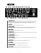
Front Panel 7 6 9 8 18 10 17 11 19 12 20 13 23 14 21 15 16 5 22 25 26 24 5. POWER/STATUS LED Located on front panel this LED illuminates green when the Power Switch is in the “ON” position and AC power is supplied. During normal operation the LED also acts as a DDT indicator. The LED illuminates red when the DDT speaker protection is active. When DDT is defeated, the LED will illuminate red when clipping occurs. 6.
16. VOLUME CONTROL Controls the overall volume level of the amplifier. The final level adjustment should be made after the desired sound has been achieved. 17. LINE OUT—XLR JACK Provides low impedance, electronically balanced signal for patching into a sound reinforcement or recording console. 18. LINE OUT LEVEL CONTROL Controls the output level of the balanced line out. 19.
MAX® 450 SPECIFICATIONS SYSTEM SPECIFICATIONS: PREAMPLIFIER SECTION: SETTINGS FOR MEASUREMENTS UNLESS OTHERWISE NOTED: Mains Fuse = 8 amps Mains Voltage = 120 VAC 60 Hz Power Consumption = 350 watts Hum and noise: Typically greater than -89 dB unweighted with controls set as follows… Pad = Passive Bright = Normal Pre gain = 5 Contour = 0 Low = 0 Mid = 0 Mid Shift = 1kHz High = 0 Volume = 5 Pad = out (Passive) Bright = out (Normal) Pre-Gain = 5 (12 o’clock) Contour = 0 (fully counterclockwise) Bass = 0 (1
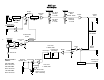
MAX® 450 Block Diagram Shelving EQ Bright Infrasonic Filter Input -10 db Pad 1 High Shelf (Treble) +/- 15 dB Midrange Shift 200HZ - 2KHZ Low Shelf (Bass) +/- 15 dB Midrange Cut/Boost +/- 15 dB Buffer Contour Gain 2 -10 db Pad In/Out Midrange Effects Send PreGain Tuner Send Instrument Level Effects Loop -10 dB, 0, 315 VRMS Buffer Pre/Post EQ Select 9 Balanced Line Out + 2 3 1 Pre EQ Post EQ Line Level Out CW - Line Level 1 VRMS, 0dB Line Drivers Pwr Amp In Ground Lift Minimum Load is
MAX® 450 Recommend Settings Rock Setting Out Set to appropriate level for instrument used Set to necessary NOTE: “DDT should be utilized for maximum speaker protection” Slap Setting In Set to appropriate level for instrument used Set to necessary NOTE: “DDT should be utilized for maximum speaker protection” Blues/ Country Setting Out Set to appropriate level for instrument used Set to necessary NOTE: “DDT should be utilized for maximum speaker protection” 10
ESPAÑOL MAX® 450 Amplificador profesional para bajo Felicitaciones por tu compra del MAX® 450 de Peavey. El MAX 450 incluye un ecualizador activo de tres bandas con control de cambio de medios y control de silueta que es fácil de usar (para lograr esa curva de ecualización de cara feliz). Estos controles de tono son tan versátiles que podrás obtener tu sonido muy rápidamente.
Panel Trasero 4 1 2 3 CARACTERÍSTICAS DE PODER CA: 1. CABLE DE PODER CA INTERCAMBIABLE Esta entrada es para el cable de línea IEC (incluido), mismo que provee poder CA a la unidad. Conecta el cable de línea a este conector y a un suministro de CA propiamente aterrizado. El equipo puede dañarse si se usa voltaje de línea inapropiado. (Ver marcación de voltaje en la unidad). Nunca quites ni cortes el alfiler de tierra del conector del cable de línea. Esta unidad viene con un cable de marcación correcta.
Panel Frontal 7 6 9 8 18 10 17 11 19 12 13 20 23 14 21 15 16 5 22 25 26 24 5. LED DE ESTADO DE PODER Localizado en el panel frontal este LED se ilumina de verde cuando el interruptor de poder esté en la posición ON y se esté suministrando poder CA. Durante la operación normal el LED también actúa como indicador de DDT. El LED se iluminará de rojo cuando esté activada la protección de bocinas DDT. Cundo se cancele la DDT, el LED se iluminará de rojo si ocurre la saturación. 6.
15. CONTROL DE AGUDOS Un control de tono activo (tipo shelving, ±15 dB) que varía el aumento o corte de las frecuencias agudas. 16. CONTROL DE VOLUMEN Controla el volumen general del amplificador. El nivel final de ajuste debe ser hecho después de que se ha logrado el sonido deseado. 17. CONECTOR XLRSALIDA DE LÍNEA Provee un señal balanceada y de baja impedancia para parchar a una consola de refuerzo de sonido o grabación. 18.
Max 450™ ESPECIFICACIONES ESPECIFICACIONES DEL SISTEMA SECCIÓN DE PREAMPLIFICADOR: Fusible principal = 8 amps Voltaje = 120 VAC 60 Hz Consumo de poder = 350 wats Hum y ruido: Típicamente mayor que -89 dB sin peso con controles ajustados como sigue: Pad = pasivo Brillante = Normal Pre ganancia = 5 Silueta = 0 Graves = 0 Medios = 0 Cambio de Medios = 1kHz Agudos = 0 Volumen = 5 VALORES PARA MEDIDAS AL MENOS QUE SE INDIQUE LO CONTRARIO: Pad = salida (pasivo) Brillante = salida (Normal) Pre-gnancia = 5 (12 e
FRANCAIS MAX® 450 AMPLIFICATEUR BASSE Nous vous félicitons pour l’achat de cet amplificateur Peavey MAX® 450. Le MAX 450 possède un EQ actif 3-bandes avec réglage semi-paramétrique des mediums et un contrôle de contour (pour obtenir aisément la populaire equalisation en V). Ces contrôles de tonalité assurent au MAX 450 une versatilité optimum qui vous permettra de trouver rapidement votre son.
Face Arriere 4 1 2 3 CARACTERISTIQUES D’ALIMENTATION: 1. CONNECTEUR IEC Pour votre securite, un cordon d’alimentation assurant une bonne connexion a la terre est inclus. La connexion a la terre ne doit etre deconnectee en aucune circonstance. Les risques de choc electrique sont considerablement reduits lorsque la masse du chassis est correcte ment reliee a la terre. Reportez-vous aux inscriptions au dos de votre amplificateur pour la tension d’alimentation necessaire. 2.
Face Avant 7 6 9 8 18 10 17 19 11 12 20 13 23 14 21 15 16 5 22 25 26 24 5. LED DE STATUT ET D’ALIMENTATION Lorsque le commutateur d’alimentation est sur la position “on”, la LED s’illumine en vert. Cette LED joue aussi le rôle d’indicateur DDT. Elle deviendra rouge si la compression DDT se met en action. Si la DDT n’est pas utlisée, la LED s’illuminera en rouge en cas d’écrêtage. 6. ENTREE Cette entrée fonctionne pour tous les types de basses. 7.
12. CONTROLE LOW Contrôle de tonalité actif (±15 dB) augmentant ou atténuant les fréquences graves. 13. CONTROLE MID Contrôle de tonalité actif (±15 dB) augmentant ou atténuant les fréquences moyennes. 14. CONTROLE MID SHIFT Détermine la bande de fréquences sur laquelle agît le contrôle mid. 15. CONTROLE HIGH Contrôle de tonalité actif (±15 dB) augmentant ou atténuant les fréquences aigues. 16. CONTROLE VOLUME Détermine le volume général de l’amplificateur.
27. PATTES D’ENROULEMENT Utilisez ces pattes pour enrouler votre cordon d’alimentation lors du rangement ou du transport de votre amplificateur FireBass 700. Déconnectez le cordon d'alimentation de l’amplificateur avant de l’enrouler. 28. SORTIES HP Ces deux prises jacks constituent la sortie de l’amplificateur. Ces deux sorties sont identiques et connectées en parallèle. L’impédance minimum en sortie de l'amplificateur doit être de 2 Ohm (soit deux enceintes de 4 Ohm en parallèle).
Max® 450 SPECIFICATIONS SYSTEM SPECIFICATIONS: PREAMPLIFIER SECTION: SETTINGS FOR MEASUREMENTS UNLESS OTHERWISE NOTED: Mains Fuse = 8 amps Mains Voltage = 120 VAC 60 Hz Power Consumption = 350 watts Hum and noise: Typically greater than -89 dB unweighted with controls set as follows… Pad = Passive Bright = Normal Pre gain = 5 Contour = 0 Low = 0 Mid = 0 Mid Shift = 1kHz High = 0 Volume = 5 Pad = out (Passive) Bright = out (Normal) Pre-Gain = 5 (12 o’clock) Contour = 0 (fully counterclockwise) Bass = 0 (1
DEUTSCH MAX® 450 PROFESSIONELLER BASS-VERSTÄRKER Wir freuen uns, dass Sie sich für einen Peavey MAX 450™-Bassverstärker entschieden haben. Die Klangregelung des MAX 450 besteht aus einem aktiven Dreiband-EQ mit parametrischer Mittenregelung sowie einem zusätzlichen Contour-Regler (für die typische EQ-"U-Form") und ist damit so vielseitig, dass Sie Ihren Sound schnell gefunden haben dürften.
Rear Panel 4 1 2 3 STROMVERSORGUNG: 1. Separates Netzkabel Diese Buchse ist für das Euro-Netzkabel zur Stromversorgung des Geräts (im Lieferumfang enthalten) vorgesehen. Schließen Sie das Netzkabel ausschließlich an einen korrekt geerdeten Netzanschluss mit geeigneter Spannung an (siehe Aufschrift Geräterückseite), da das Gerät sonst ernstlichen Schaden nehmen kann. Entfernen oder umgehen Sie niemals den Massepunkt am Netzkabel selbst. Bei Auslieferung liegt dem Gerät ein geeignetes Netzkabel bei.
5. POWER/STATUS-LED Auf der Frontplatte befindet sich eine LED, die grün leuchtet, wenn sich der Netzschalter in Position “ON” befindet und dem Gerät Strom zugeführt wird. Im Normalbetrieb fungiert diese LED gleichzeitig als DDT-Anzeige. Bei aktivierter DDT-Lautsprecher-Schutzschaltung leuchtet die LED rot; bei nicht aktivierter DDT-Schutzschaltung leuchtet die LED rot auf, sobald das Gerät übersteuert. 6. INPUT (Eingang) Der Eingang des MAX 450 eignet sich für alle Arten von Bass-Tonabnehmern. 7.
20. GROUND LIFT Dieser Schalter trennt den XLR-Ausgang zur Vermeidung von Brummschleifen von der Gerätemasse. 21. EFFECTS SEND Dieser Ausgang dient der Überführung des Signals an ein externes, niedrigpegeliges Effekt- oder anderes Signalbearbeitungsgerät. 22. EFFECTS RETURN Dieser Eingang dient der Rückführung des Signals von einem externen, niedrigpegeligen Effekt- oder anderen Signalbearbeitungsgerät. 23.
Max® 450 SPECIFICATIONS TECHNISCHE DATEN: VORVERSTÄRKER: Netzsicherung = 8 A Netzspannung = 120 VAC 60 Hz Leistungsaufnahme = 350 W Rauschabstand: typisch > -89 dB, unbewertet, Reglerstellung wie folgt: Pad = Passive Bright = Normal Pre-Gain = 5 Contour = 0 Low = 0 Mid = 0 Mid Shift = 1kHz High = 0 Volume = 5 GEMESSEN BEI FOLGENDER REGLERSTELLUNG (ABWEICHUNGEN AUSDRÜCKLICH GEKENNZEICHNET): Pad = nicht gedrückt (Passive) Bright = nicht gedrückt (Normal) Pre-Gain = 5 (12-Uhr-Stellung) Contour = 0 (Linksans
PEAVEY ELECTRONICS CORPORATION LIMITED WARRANTY Effective Date: July 1, 1998 What This Warranty Covers Your Peavey Warranty covers defects in material and workmanship in Peavey products purchased and serviced in the U.S.A. and Canada.
Features and specifications subject to change without notice. Peavey Electronics Corporation • 711 A Street • Meridian, MS 39301 (601) 483-5365 • FAX (601) 486-1278 • www.peavey.com ©2003 80304957 Printed in the U.S.A.