User Manual MMA™ Mixer/Power Amplifier System MMA81502 · MMA8752 · MMA8352
Intended to alert the user to the presence of uninsulated “dangerous voltage” within the product’s enclosure that may be of sufficient magnitude to constitute a risk of electric shock to persons. Intended to alert the user of the presence of important operating and maintenance (servicing) instructions in the literature accompanying the product. CAUTION: Risk of electrical shock — DO NOT OPEN! CAUTION: To reduce the risk of electric shock, do not remove cover. No user serviceable parts inside.
IMPORTANT SAFETY INSTRUCTIONS WARNING: When using electrical products, basic cautions should always be followed, including the following: 1. 2. 3. 4. 5. 6. 7. 8. 9. 10. 11. 12. 13. 14. 15. 16. 17. 18. Read these instructions. Keep these instructions. Heed all warnings. Follow all instructions. Do not use this apparatus near water. Clean only with a dry cloth. Do not block any of the ventilation openings. Install in accordance with manufacturer’s instructions.
ENGLISH MMA™ Mixer/Power Amplifier Systems Description: The MMA™ 81502‚ 8752 and 8352 are high-quality‚ industrial-grade audio mixer/amplifiers. Designed for flexibility in application‚ these mixer/amps represent the latest‚ state-of-the-art technology in mixer/amplifier design. Powerful‚ yet easy to use‚ the MMA series delivers amazing sonic performance.
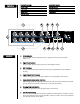
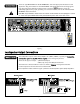
Applications Front Panel · · · · · · presentation rooms board rooms courtrooms auditoriums lecture halls meeting rooms · · · · · convention centers paging systems background music retail spaces restaurants 1. Power Indicator The green LED indicates when AC power is supplied to the unit and the power switch is on. 2. Signal Level Indicator The green LED indicates signal presence at the amplifier output. 3. SPS ™ I n d i c a t o r The red LED indicates when SPS circuitry is active.
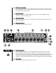
Rear Panel 8. High EQ Control (Treble) This is an active equalization control that adjusts the high frequency. Clockwise rotation boosts high frequencies and counter-clockwise rotation provides a cut in high frequencies (±10 dB). EQ is flat at center detent. 9. EQ Bypass Switch Selects the status of the EQ. When OUT the EQ controls are active. When IN the EQ controls are inactive and the EQ is flat. 10. Mute Bus Indicators The red LEDs indicate the status of each mute bus.
14. Fuse The fuse is located within the cap of the fuse holder. If the fuse fails, THE FUSE MUST BE REPLACED WITH THE SAME TYPE AND VALUE IN ORDER TO AVOID DAMAGE TO THE EQUIPMENT AND TO PREVENT VOIDING THE WARRANTY. If the amp repeatedly blows fuse, it should be taken to a qualified service center for repair. WARNING: The fuse should only be replaced when the power cord has been disconnected from its power source! 15.
21. Power Amplifier Input Provides a direct input to the power amplifier with an input sensitivity of 1 Volt. When an RCA phono plug is inserted into this input, the connection between the preamp output and the power amp input is internally disconnected allowing direct access to the power amplifier. Using this input along with the preamplifier output (#9), a signal processor can be inserted between the mixer and the power amplifier. 22.
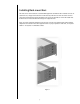
Installing Rack-mount Ears This unit can be rack-mounted in a standard EIA equipment rack with the two included rack ears. To attach the ears‚ simply remove the three screws already in the front of each side of the unit and align the ears with the appropriate mounting holes. It may be desirable to remove the rubber feet from the bottom of the unit when mounting in an equipment rack.
Input Connections There are eight INPUT PORTS for PLUG-IN MODULES. Select the appropriate modules for each application. Plug the modules into the INPUT PORTS. Slide them between the card-edge guide rails and secure them with the provided screws as shown in Figure 3 . Ensure screws are sufficiently tightened for proper grounding. For connection details, refer to the individual PLUGIN MODULE Instruction Guide. CAUTION: Plug-in Modules should not be inserted or removed while the mixer/amplifier is turned on.
MMA81502 (230V) The loudspeaker outputs of the mixer/amplifier are 4 Ohms, 8 Ohms, 70V and 100V. Connect the loudspeaker system to any ONE of these outputs. Class 2 wiring may be used. There are two types of output: 4 Ohm Direct Output; 8 Ohm, 70V, and 100V via Output Transformer The method of connection differs in each case. Refer to Figure 5 . If using the transformer isolated outputs be sure that the Low Cut switch is ON.
MMA8352 (120V) The loudspeaker outputs of the mixer/amplifier are 4 Ohms, 8 Ohms, 70V and 100V. Connect the loudspeaker system to any ONE of these outputs. Class 2 wiring may be used. There are two types of output: 4 Ohm Direct Output; 8 Ohm, 70V, and 100V via Output Transformer The method of connection differs in each case. Refer to Figure 7 . If using the transformer isolated outputs be sure that the Low Cut switch is ON.
Block Diagram 13
Specifications Rated Output Power: Rear Panel Features: MMA81502: 150 W MMA8752: 75 W MMA8352: 35 W Preamp Output Power Amp Input Program Input Bridge In/Out External Mute Terminals External Volume Control Plug-in Module Ports 1–8 Loudspeaker Output Terminals AC convenience outlet (120V units only) Power Switch Fuse IEC Power Connector Output Regulation: Direct Out: ± 0.5dB Transformer Out: ± 1.0dB Frequency Response: Power Amplifier: ±0.5 dB, 20 Hz to 20 kHz, Direct Out ±1.
DEUTSCH MMA™ Mixer/Power Amplifier Systems Description: Die Modelle MMA™ 81502, 8752 und 8352 sind hochwertige Audio-Mischpulte/Verstärker für den gewerblichen Einsatz. Diese Mischpulte/Verstärker zeichnen sich durch ihre Flexibilität in der Anwendung aus und sind mit der modernsten und fortschrittlichsten Technologie im Bereich dieser Geräte ausgestattet. Die leistungsfähige und gleichzeitig anwenderfreundliche MMA-Baureihe bietet eine ausgezeichnete Klangleistung.
Einsatzbereiche Front Panel ·Präsentationsräume · Sitzungssäle · Gerichtssäle · Hörsäle · Vorlesungssäle · Besprechungsräume · · · · · Messe- und Konferenzzentren Paging-Systeme Hintergrundmusik Einzelhandelsgeschäfte Restaurants 1. Betriebsanzeige Die grüne LED leuchtet auf, wenn das Gerät mit Wechselstrom versorgt wird und eingeschaltet ist. 2. Signal-Level-Anzeige Diese grüne LED leuchtet auf um anzuzeigen, dass ein Signal am Verstärkerausgang vorliegt. 3.
13 14 8. High-EQ-Regler (Treble) Hier handelt es sich um einen aktiven Equalizer-Regler, mit dem die hohen Frequenzen eingestellt werden. Durch Drehen im Uhrzeigersinn werden die hohen Frequenzen angehoben, durch Drehen im entgegengesetzten Uhrzeigersinn werden sie abgesenkt (±10 dB). Steht der EQ-Regler auf der mittleren arretierten Position, sind die Frequenzen unverändert. 9. EQ-Bypass-Schalter Hiermit wird der Status des EQ ausgewählt. Ist er ausgeschaltet, sind die EQ-Regler aktiv.
GARANTIE ZU VERHINDERN. Sollte die Sicherung des Gerätes wiederholt durchbrennen, muss es zu einem qualifizierten Servicecenter zur Reparatur gebracht werden. ACHTUNG: Die Sicherung darf nur ausgetauscht werden, wenn das Netzkabel von der Stromquelle abgetrennt wurde! 15. Wechselstromanschluss (nicht geschaltet) Diese Steckdose liefert Strom für Zusatzgeräte mit einer Leistungsaufnahme von unter 300 W. Diese Steckdose wird nicht über den Netzschalter (Nr. 13) geregelt. 16.
21. Power Amplifier Input Dieser Anschluss bietet einen direkten Eingang zum Verstärker mit einer Eingangsempfindlichkeit von 1 Volt. Wird ein RCA-Phono-Stecker in diesen Eingang eingesteckt, wird der Anschluss zwischen Vorverstärkerausgang und Verstärkereingang intern getrennt, so dass die Signale direkt an den Verstärker gesendet werden. Über diesen Eingang zusammen mit dem Vorverstärkerausgang (Nr. 9) kann ein Signalprozessor zwischen Mischpult und Verstärker eingeschleift werden. 22.
Installation der Rack-Montageösen Dieses Gerät kann mit Hilfe der beiden beiliegenden Rack-Ösen in einem genormten EIAGeräte-Rack montiert werden. Zur Befestigung der Ösen brauchen Sie einfach nur die drei Schrauben zu entfernen, die sich vorne an beiden Seiten des Gerätes befinden, und die Ösen an den jeweiligen Montageöffnungen auszurichten. Für die Montage im Rack können die Gummifüße an der Unterseite des Gerätes bei Bedarf entfernt werden.
Eingangsanschlüsse Es stehen acht EINGANGSANSCHLÜSSE für PLUG-IN-MODULE zur Verfügung. Wählen Sie für den jeweiligen Anwendungszweck das geeignete Modul aus. Stecken Sie das bzw. die Module in die EINGANGSANSCHLÜSSE. Schieben Sie sie zwischen die Kontaktführungsschienen ein, und befestigen Sie sie mit den beiliegenden Schrauben (siehe Abbildung 3) . Achten Sie darauf, dass die Schrauben fest angezogen sind, sodass sie korrekt geerdet sind.
MMA81502 (230 V) Die Lautsprecherausgänge des Mischpults/Verstärkers sind für 4 Ohm, 8 Ohm, 70 V und 100 V ausgelegt. Schließen Sie das Lautsprechersystem an EINEN dieser Ausgänge an . Es kann Verdrahtung Klasse 2 verwendet werden. Es gibt zwei Arten von Ausgängen: Direkter Ausgang, 4 Ohm, 8 Ohm, 70 V und 100 V über Output Transformer Für beide ist ein unterschiedliches Anschlussverfahren erforderlich (siehe Abbildung 5).
MMA8352 (120V) Die Lautsprecherausgänge des Mischpults/Verstärkers sind für 4 Ohm, 8 Ohm, 70 V und 100 V ausgelegt. Schließen Sie das Lautsprechersystem an EINEN dieser Ausgänge an. Es kann Verdrahtung Klasse 2 verwendet werden. Es gibt zwei Arten von Ausgängen: Direkter Ausgang, 4 Ohm, 8 Ohm, 70 V und 100 V über Output Transformer. Für beide ist ein unterschiedliches Anschlussverfahren erforderlich (siehe Abbildung 7) .
Specifications Rated Output Power: Rear Panel Features: MMA81502: 150 W MMA8752: 75 W MMA8352: 35 W Preamp Output Power Amp Input Program Input Bridge In/Out External Mute Terminals External Volume Control Plug-in Module Ports 1–8 Loudspeaker Output Terminals AC convenience outlet (120V units only) Power Switch Fuse IEC Power Connector Output Regulation: Direct Out: ± 0.5dB Transformer Out: ± 1.0dB Frequency Response: Power Amplifier: ±0.5 dB, 20 Hz to 20 kHz, Direct Out ±1.
FRANÇAIS MMA™ Mixer/Power Amplifier Systems Description: Les MMA™ 81502‚ 8752 et 8352 sont des amplificateurs de hautes qualités destinés aux installations professionnelles. D’une grande flexibilité d’utilisation, ces unités représentent le ‘dernier cri’ en matières de technologies analogiques. Puissants, simples d’utilisation, les unités de la série MMA délivrent des performances incroyables.
Applications · · · · · · · Salles de présentation Salles de conférence Salles d’attente Auditoriums Salles de lecture Salles de réunion Centre de convention · · · · Systèmes d’appel (Paging) Musique de fond Espaces de vente Restaurants 1. Power Indicator Cette Led verte s’illumine pour indiquer que votre unité est sous tension 2. Signal Level Indicator Cette Led verte s’illumine lorsqu’un signal est présent aux entrées de votre unité de puissance. 3.
13 14 8. High EQ Control (Treble) Ce contrôle actif vous permet de varier le niveau des fréquences aigues du signal entre –10 dB et +10 dB. En le tournant horairement, vous augmentez ce niveau, et vice versa. 9. EQ Bypass Switch Vous permet d’appliquer/non-appliquer l’équalisation à votre signal. En position sortie, l’EQ est active, en position enfoncée, elle est n’est pas appliquée à votre signal. 10. Mute Bus Indicators Ces Leds rouges vous indiquent le statut des bus Mute.
14. Fuse Le fusible se trouve dans le porte fusible situé sur le panneau arrière de votre unité. Si le fusible est défectueux, IL DOIT ETRE REMPLACE PAR UN AUTRE DE MEME TYPE ET VALEUR POUR EVITER TOUT DOMMAGE A VOTRE UNITE. Si le fusible saute régulièrement, votre unité doit être vérifiée par un technicien agréé. ATTENTION: Votre unité doit être mise hors tension avant d’envisager de manipuler le fusible. 15.
21. Power Amplifier Input Cette entrée vous permet d'envoyer un signal ligne 1V directement dans l'ampli de puissance de votre unité. Combinée avec la sortie Pré-ampli, un processeur d'effets externe peut-être utilisé pour traiter le signal. 22. Bridge In/Out Vous donne un signal de sortie non altéré par les contrôles de volume (Master Level) et tonalité (Low et High).
Installing Rack-mount Ears Votre unité peut-être rackée grâce aux oreilles de fixation (fournies). Pour les assembler sur votre unité, simplement dévissez les 3 vis de chaque côté de celle-ci, positionner les oreilles puis reserrer les vis en position. Vous pouvez positionner les oreilles de différentes facons afin d'obtenir plusieurs sens de fixation pour votre unité. Référez-vous aux figures ci-dessous pour de plus amples informations.
Input Connections Votre unité est équipée de 8 ports d’entrées pour des modules MMA™. Sélectionner les modules nécessaires en fonction de l’application. Branchez les modules, positionnez-les suivants les guides de métal puis fixez-les en place grace aux vis fournies (Figure 3 ). Assurez-vous que les vis soient proprement serrés pour le contact de masse. Pour plus de détails sur les connexions de vos modules , reportez-vous à leurs manuels respectifs.
MMA81502 (230V) Les sorties enceintes de votre unité sont 4 Ohms, 8 Ohms, 25V et 70V. Connectez la charge d’enceinte à UNE SEULE de ces sorties. On pourra utiliser du cable Class2. Il existe deux types de sorties: 4 Ohm / Sortie directe ; 8 Ohm, 25V, and 70V via Output Transformer Les connexions dans chaque cas sont différentes. Reportez-vous à la Figure 5 . Si vous utilisez une sortie à transformateur, assurez-vous que le filtre coupe-bas est engagé.
MMA8352 (120V) Les sorties enceintes de votre unité sont 4 Ohms, 8 Ohms, 25V et 70V. Connectez la charge d’enceinte à UNE SEULE de ces sorties. On pourra utiliser du cable Class2. Il existe deux types de sorties: 4 Ohm / Sortie directe ; 8 Ohm, 25V, and 70V via Output Transformer Les connexions dans chaque cas sont différentes. Reportez-vous à la Figure 7 Si vous utilisez une sortie à transformateur, assurez-vous que le filtre coupe-bas est engagé.
ESPAÑOL MMA™ Mixer/Power Amplifier Systems Description: Las MMA™ 81502‚ 8752 y 8352 son mezcladoras/amplificadores de alta calidad de grado industrial. Han sido diseñadas para ofrecer flexibilidad en aplicaciones y representan lo último en tecnología en diseño de mezcladoras/amplificadores. Potente pero fácil de usar, la serie MMA ofrece calidad de sonido increíble.
Applications PANEL FRONTAL · · · · · · · Cuartos de presentación Cuartos de juntas Cortes Auditorios Salas de lectura Salones de funciones Centros de convenciones 1. · · · · Sistemas de voceo Música ambiental Tiendas Restaurantes Indicador de Corriente Este LED verde indica cuando la unidad está recibiendo corriente CA y el interruptor de corriente está encendido. 2. Indicador de Nivel de Señal Este LED verde indica la presencia de señal a la salida del amplificador. 3.
8. Control de Ecualización Aguda (Altos) Este es un control de ecualización activo que ajusta las frecuencias agudas. La rotación en dirección de las manecillas del reloj incrementa las frecuencias agudas y la rotación en dirección contraria provee un recorte en las frecuencias agudas (±10 dB). El ecualizador está en posición plana en el centro marcado. 9. Interruptor de Bypass del Ecualizador Selecciona el estatus del ecualizador. Cuando está fuera el ecualizador está activo.
14. Fusible El fusible está localizado en la tapa del orificio del fusible. Si el fusible falla, EL FUSIBLE DEBE SER REEMPLAZADO CON UNO DE LAS MISMAS CARATERÍSTICAS PARA PREVENIR DAÑOS AL EQUIPO Y PARA PREVENIR LA CANCELACIN DE LA GARANTÍA. Si el amplificador vuela fusibles repetidamente, debe ser llevada a un centro de servicio calificado para que sea reparada. CUIDADO: El fusible sólo debe ser reemplazado cuando el cable de corriente ha sido desconectado de la fuente de energía. 15.
21. Entrada del Amplificador de Poder Provee una entrada directa al amplificador con una sensibilidad de entrada de 1 Voltio. Cuando se inserta un conectador RCA phono en esta entrada, la conexión entre la salida del preamp y el amplificador de poder es desconectada internamente permitiendo acceso directo al amplificador. Usar esta entrada a la vez que la salida del preamplificador (#9), un procesador de señal puede ser insertado entre la mezcladora y el amplificador. 22.
Instalación de orejas para rack Esta unidad puede ser montada en un rack estándar EIA con las dos orejas incluidas. Para instalar las orejas, simplemente hay que quitar los tres tornillos en el frente de cada lado de la unidad y alinear las orejas con los orificios de montura. Puede ser recomendable quitar las patas de hule de la parte inferior de la unidad cuando se monta en un rack.
Conexiones de Entrada Hay ocho PUERTOS DE ENTRADA para MÓDULOS PULG-IN. Se deben seleccionar los módulos apropiados para cada aplicación. Conecta los módulos en los PUERTOS DE ENTRADA. Estos se resbalan a su posición y luego deben ser asegurados con sus respectivos tornillos como se muestra en la figura 3. Hay que verificar que los tornillos estén lo suficientemente ajustados para que se aterricen propiamente. Para detalles de conexión, por favor leer los instructivos de cada MÓDULO PLUG-IN.
MMA81502 (230V) Las salidas para parlantes de la mezcladora/amplificador son de 4 ohmios, 8 Ohmios, 70V y 100V. El sistema de parlantes debe ser conectado solamente a una de estas salidas. Se puede usar cableado de clase 2. Hay dos tipos de salida: Salida Directa de 4 Ohmios Salida de Transformador de 8 Ohmios, 25V y 70 V Nota: Los valores de impedancia mostrados en la Figura 5 indican carga total de impedancia del sistema.
MMA8352 (120V) Las salidas para parlantes de la mezcladora/amplificador son de 4 ohmios, 8 Ohmios, 70V y 100V. El sistema de parlantes debe ser conectado solamente a una de estas salidas. Se puede usar cableado de clase 2. Hay dos tipos de salida: Salida Directa de 4 Ohmios Salida de Transformador de 8 Ohmios, 70V y 100 V El método de conexión difiere en cada caso. Ver la Figura 7 . Si se usan las salidas de transformador aislado, hay que asegurarse que el filtro de graves está encendido.
Specifications Rated Output Power: Rear Panel Features: MMA81502: 150 W MMA8752: 75 W MMA8352: 35 W Preamp Output Power Amp Input Program Input Bridge In/Out External Mute Terminals External Volume Control Plug-in Module Ports 1–8 Loudspeaker Output Terminals AC convenience outlet (120V units only) Power Switch Fuse IEC Power Connector Output Regulation: Direct Out: ± 0.5dB Transformer Out: ± 1.0dB Frequency Response: Power Amplifier: ±0.5 dB, 20 Hz to 20 kHz, Direct Out ±1.
NOTES: 44
NOTES: 45
NOTES: 46
WARRANTY Architectural Acoustics® PEAVEY ELECTRONICS CORPORATION LIMITED WARRANTY Effective Date: July 1, 1998 What This Warranty Covers Your Peavey Warranty covers defects in material and workmanship in Peavey products purchased and serviced in the U.S.A. and Canada.
80304722 Peavey Electronics Corporation • 711 A Street • Meridian, MS 39301 601-483-5376 • Fax 601-486-1678 • http://aa.peavey.com ©2002 Printed in the U.S.A.