P C X V 1 2 True diversity VHF wireless receiver OPERATING GUIDE
Intended to alert the user to the presence of uninsulated “dangerous voltage” within the product’s enclosure that may be of sufficient magnitude to constitute a risk of electric shock to persons. Intended to alert the user of the presence of important operating and maintenance (servicing) instructions in the literature accompanying the product. CAUTION: Risk of electrical shock — DO NOT OPEN! CAUTION: To reduce the risk of electric shock, do not remove cover. No user serviceable parts inside.
INTRODUCTION Thank you for selecting a Peavey Pro Comm PCXV12 quartz controlled single channel true diversity wireless microphone system. Before operating and installing this system please read this instruction manual carefully and thoroughly in order to attain the correct operating procedures and to achieve the best results. True Diversity Receiver The Peavey Pro Comm PCX-V12 quartz controlled receiver is a true diversity wireless system.
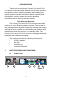
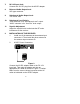
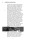
1. Antenna Input Connector A 2. Power Switch and Indicator: When the switch is turned on the red indicator illuminates to denote normal power status. 3. RF Signal Level Indicator: Indicates the RF signal strength received from the microphone. As soon as the signal is emitted from the microphone the LED indicator illuminates. 4. Audio Signal Level Indicator: Indicates the audio signal level. As soon as the microphone signal is modulated, the LED indicator illuminates. 5.
7. DC 12V Input Jack: Connect the 12V DC plug from the AC/DC adapter. 8. Balanced Audio Output Jack: XLR type connector 9. Unbalanced Audio Output Jack: 1/4" Phone Jack 10. Unbalanced Level Switch: “LOW selection is for “Microphone-Level” output. “HIGH” selection is for “Line-Out” level output. 11. Squelch Adjustment: Adjust the squelch level to eliminate the RF noise interference at the receiver. 2. INSTALLATION OF THE RECEIVER 1. Install one of the antennas at the antenna input connector A.
3. c. Audio Output Connection: a. Unbalanced Level Switch Setting Position: Make sure to match the unbalanced output setting to the device input setting. The incorrect setting could result in low sensitivity level or over load distortion. Ex. (If you are going into the “Line” input on a mixer or amplifier then the switch should be set to the high position. If you are going into the “Mic” input of an amplifier or mixer then the switch should be set to the low position.) b.
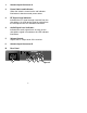
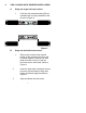
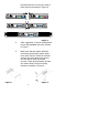
3. TWO 19/2-INCH UNITS RECEIVER INSTALLATION A. Setup for single half-rack receiver 1. Push the rack mount brackets (RM-11) upwards until it is firmly attached to the receiver. (Figure 5) Figure 5 Setup for dual half-rack receivers B. 1. Remove the screws at the top and bottom of the receiver where they will be joined together. Remove one steel plate from each receiver. Push the receivers next to each other. Refer to Figure 6. 2. Insert the steel plate in between the two receivers (top and bottom).
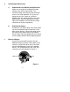
brackets (RM-12) on the outer sides of both receivers as shown in Figure 6. 4. 5. Figure 6 After completion, it can be rackmounted into an EIA standard rack case. Shown in Figure 7. Make sure that the system performs correctly by placing the system away from noise sources. Place the receiver at least one meter above the ground and one meter away from noise sources. Place the microphone at least one meter away from the receiving antenna, as shown in Figure 8.
4. OPERATION INSTRUCTIONS 1. Turn the volume controls of the receiver and device in use to a minimum setting before turning on the microphone transmitter. After the receivers power switch is set to the on position, the power switch’s red indicator illuminates to denote normal power status. 2. If the SIGNAL LED indicators of the receiver are illuminated before switching on the microphone or transmitter, it indicates the receiver is receiving interference signals.
microphone the AUDIO LED indicators will illuminate according to the strength of sound level. If the LEDs do not illuminate or sound is not present at the output, the system is not functioning properly and must be checked. 4. Receiver and Amplifier Volume Adjustment: a. Single-channel Unbalanced Audio Output: Switch the level switch on the rear panel of the receiver to the left “LOW” Position, then adjust the volume control to twelve o’clock position.
IN” input jack of the amplifier or mixer. Adjust the volume controls of the amplifier or mixer to the same desired level, then properly fine adjust the receiver volume control to match the same sensitivity as the wired microphone. d. 5. If the receiver output level is adjusted to a level that is near the maximum input level of the desired device, it will cause saturation distortion of the device when the receiver output level is increased due to a increase in level by the sound source.
5. Caution 1. 2. Since the installation of the antenna influences the operating efficiency of the receiver, the most important rule is to minimize the distance as much as possible between the receiving antenna and the microphone for the best reception and performance. The output voltage of the external DC power supply should not be below 12V, otherwise it will not work properly. If the voltage is over 15V some components of the receiver will be damaged due to excessive current draw.
HANDHELD WIRELESS MICROPHONE The Peavey Pro Comm PCX-V12 handheld wireless microphone is a modular design. It also incorporates “Superior frequency tracking and muting techniques” dualsquelch to eliminate noise interference. 5 4 3 2 1 Unit Features and Functions 1. Grille: Protects cartridge and prevents breathing and wind POP noises. 2. Housing: Upper portion that is connected to the capsule module. Internally it holds the transmitter PCB and battery compartment. 3.
2. BATTERY INSERTION Figure 12 1. Unscrew the battery cap in a counterclockwise direction. 2. Insert a 9V battery into the battery compartment according to the correct polarity as shown in Figure12. The moment the battery touches the terminals of the compartment, the indicator will flash briefly. This means the polarity is correct. However, if no flash occurs, this indicates wrong insertion or battery is dead.
4. When the microphone is not in use make sure to turn it off to extend the battery life. Remove the battery from the battery compartment if the microphone will not be in use for a long period of time. If a rechargeable battery is used take it out for a recharge as necessary. BELT PACK TRANSMITTER 1. Unit Features and Functions 1. 4-pin Jack Input Connector: Connects to the Peavey Pro Comm 4-pin connector.
4. Gain Control: Adjusts the input gain to an appropriate level. 5. Transmitter Housing: Contains the PCB and battery. 6. Battery Status Indicator: Indicates the power on/off and battery status. a. When the power switch is turned on the LED indicator flashes briefly, indicating normal battery status. b. If the LED illumination is sustained at either power on or during usage the battery level is low. The old battery should be replaced with a new one. 7. Power Switch: Switch to ON position for operation.
1. Push down on the battery cover to open the battery compartment. 2. Insert a 9V battery into the battery compartment according to the correct polarity as shown in Figure 14. Then push up on the battery cover to close the battery compartment. 3. The LED indicator will flash briefly when power is turned on to indicate normal battery status. If no flash occurs it has either no battery, the battery is drained or installed incorrectly. Change accordingly. 4.
3. AF 4-PIN INPUT CONNECTION METHODS 1. 2-Wire Electret condenser microphone Capsule 2. 3-Wire Electret condenser microphone Capsule 3. Dynamic Microphone 4. Electric Guitar 5.
SPECIFICATIONS 1. Overall: VHF PCX-V12 1. 2. 3. 4. 5. 6. 7. 8. 9. 10. Carrier Frequency Range: VHF Band 160~250 MHz Oscillation Mode: Quartz-controlled Channel: 1-channel fixed Stability: + 0.005 % with temperature compensation Max. Deviation: + 15 KHz with level limiting Dynamic Range: > 110 dB S/N Ratio: > 102 dB T.H.D.: < 0.5 % Squelch: “Superior frequency tracking and muting techniques” dual-squelch Frequency Response: 60 Hz~18 KHz + 3 dB 2. Receiver: VHF PCX-V12 1. 2. 3. 4. 5. 6. 7. 8. 9.
TROUBLESHOOTING GUIDE Symptom Distance Possible Cause Possible Solution No AF signal and no RF signal Any low transmitter battery voltage replace battery No AF signal and no RF signal long out of range move transmitter closer to receiver or obstecles No AF signal but normal RF signal any microphone or other input source check input source Distortion with no AF peak indication any low transmitter battery voltage replace battery Noise with low AF signal and normal RF signal any strong RF
NOTES: 21
PEAVEY ELECTRONICS CORPORATION LIMITED WARRANTY Effective Date: July 1, 1998 What This Warranty Covers Your Peavey Warranty covers defects in material and workmanship in Peavey products purchased and serviced in the U.S.A. and Canada.
IMPORTANT SAFETY INSTRUCTIONS 1. WARNING: When using electric products, basic cautions should always be followed, including the following: Read these instructions. 2. Keep these instructions. 3. Heed all warnings. 4. Follow all instructions. 5. Do not use this apparatus near water. For example, near or in a bathtub, swimming pool, sink, wet basement, etc. 6. Clean only with a damp cloth. 7. Do not block any of the ventilation openings. Install in accordance with manufacturer’s instructions.
Features and specifications subject to change without notice.