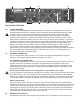
® PV SERIES AMPS STEREO POWER AMPLIFIERS O P E R AT I N G G U I D E
Intended to alert the user to the presence of uninsulated “dangerous voltage” within the product’s enclosure that may be of sufficient magnitude to constitute a risk of electric shock to persons. Intended to alert the user of the presence of important operating and maintenance (servicing) instructions in the literature accompanying the product. CAUTION: Risk of electrical shock — DO NOT OPEN! CAUTION: To reduce the risk of electric shock, do not remove cover. No user serviceable parts inside.
IMPORTANT SAFETY INSTRUCTIONS WARNING: When using electrical products, basic cautions should always be followed, including the following: 1. Read these instructions. 2. Keep these instructions. 3. Heed all warnings. 4. Follow all instructions. 5. Do not use this apparatus near water. 6. Clean only with a dry cloth. 7. Do not block any of the ventilation openings. Install in accordance with manufacturer’s instructions. 8.
PV® SERIES STEREO POWER AMPLIFIER INTRODUCTION Congratulations! You have just purchased a Peavey Electronics PV Series power amplifier. Using proven technology gained through years of amplifier design, this unit takes advantage of rugged TO-3P output devices mounted on massive aluminum extrusions and dissipates heat via an extremely quiet and effective 2speed fan.
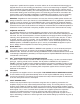
1 2 34 4 32 5 1 FRONT PANEL FEATURES (1) INPUT GAIN (dB) These controls are used to adjust the input gain of each channel. They determine how “loud” each channel of the power amplifier will sound for a given input signal level. Maximum input gain is achieved at the fully clockwise setting (+32 dB, 40 X), and this setting yields maximum mixer/system headroom. A setting of less than fully clockwise will yield lower system noise at the expense of mixer/system headroom.
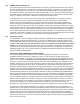
7 9 8 10 14 11 12 15 13 BACK PANEL FEATURES (6) CIRCUIT BREAKER There is one circuit BREAKER on the PV® amplifier. This breaker is provided to limit current to the associated power transformer, and protect it from overheating and possible destruction due to fault conditions in the unit. The trip current values have been carefully chosen to allow reasonable continuous power output performance, while still protecting the power transformer.
outputs are in parallel and the speaker connection cables can be terminated with banana plugs or stripped wires for use in the binding post terminals, or can be connected using the Speakon® outputs (9). For sustained high-power applications, either outputs can be used; however, exercise care to assure the correct speaker phasing. The red binding posts are the signal outputs from each channel, and the black binding posts are chassis ground.
(14) COMBO INPUT CONNECTOR The combo connector offers both female XLR and 1/4" phone jack balanced inputs for each channel. The XLR is wired with pin 1 as ground, pin 2 positive input, and pin 3 negative input. The 1/4" phone jack is a tip/ring/sleeve (3-conductor) type, with the tip being positive input, the ring negative input, and the sleeve ground.
BRIDGE MODE The Bridge mode on stereo amplifiers is often misunderstood relating to actual operation and usage. In basic terms, when a 2-channel amplifier is operated in the Bridge mode, it is converted into a single-channel unit with a power rating equal to the sum of the power rating for each channel, at a load of twice that of the single-channel rating. For example, the PV 1500 is rated at 500 watts RMS per channel into 4 ohms. The Bridge rating is 1000 watts RMS into 8 ohms (minimum load).
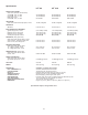
Specifications PV® 900 PV® 1500 PV® 2600 300 W RMS/chan 180 W RMS/chan 500 W RMS/chan 300 W RMS/chan 900 W RMS/chan 550 W RMS/chan 600 W RMS 1000 W RMS 1800 W RMS HUM & NOISE: Stereo mode, below rated output power, 4 ohms 100 dB, unweighted 100 dB, unweighted 100 dB, unweighted DISTORTION: SMPTE-IM Less than 0.01% Less than 0.01% Less than 0.
FRANÇAIS AMPLIFICATEURS PROFFESSIONNELS STEREO PV® SERIES INTRODUCTION Félicitations pour avoir choisi l’un des meilleurs amplificateurs de puissance! Reprenant une technologie ayant fait ses preuves, les unités PV Series utilisent un système de transistors TO-3P montés sur un radiateur aluminium refroidi par un ventilateur double-vitesse. Ils possèdent d’énormes transformateurs toroidaux et des possibilités jamais vues sur des unités à prix équivalents.
PANNEAU AVANT 1 2 34 4 32 5 1 (1) GAIN D’ENTREE(dB) Ces contrôles vous permettent d’ajuster le niveau d’entrée de chaque canal. Ils déterminent la ‘puissance’ du canal correspondant pour un signal d’entrée donné. Le gain augmente quand vous tournez horairement ce contrôle. Positionnez ces contrôles en position minimum (sens contre horaire) pour les mises sous et hors tension dans le but de protéger vos hauts-parleurs.
PANNEAU ARRIERE 6 7 9 8 10 11 14 12 15 13 (6) DISJONCTEUR Il y a un disjoncteur dans chaque unité. Il permet de limiter l’alimentation électrique et éviter toute surchauffe ou possible panne due à une mauvaise connection. La valeur de ce disjoncteur a été choisie pour permettre à votre unité de fonctionner normalement tout en protégeant votre unité. Son déclenchement ne devrait pas survenir en utilisation normale, et indique qu’un courant trop important est drainé par votre unité.
(9) SORTIES SPEAKON® Votre unité est équipée de 3 connecteurs Speakon 4-conducteurs, un par canal et un pour le mode pont (Bridge). Veuillez vous référer à la section MODE PONT avant d’utiliser ce connecteur. Pour chaque connecteur, les mêmes règles d’impédance minimale que les borniers sont à respecter. Ils sont connectés de facon standard, avec les pins 1+ et 2+ en parallèle et 1- et 2- en parallèle.
INSTALLATIONS INDUSTRIELLES ET COMMERCIALES Pour une installation dans le but d’une utilisation prolongée à gros volume, l’unité doit être montée dans un support rack standard 19". Il n’est pas nécessaire de laisser des unités vides entre les amplificateurs car la ventilation se fait dans le sens arrière-avant de votre unité. Néanmoins, une alimentation en air frais doit être prévue. Le ventilateur interne doit être capable d’envoyer de l’air non-préchauffé par un autre système.
PV® 900 PV® 1500 PV® 2600 450 W RMS/chan 300 W RMS/chan 180 W RMS/chan 750 W RMS/chan 500 W RMS/chan 300 W RMS/chan 1300 W RMS/chan 800 W RMS/chan 540 W RMS/chan 900 W RMS 600 W RMS 1500 W RMS 1000 W RMS 2600 W RMS 1800 W RMS HUM & NOISE: Stereo mode, below rated output power, 4 ohms 100 dB, unweighted 100 dB, unweighted 100 dB, unweighted DISTORTION: SMPTE-IM Less than 0.01% Less than 0.01% Less than 0.
ESPAÑOL SERIE DE AMPLIFICADORES PROFESIONALES ESTÉREO PV® INTRODUCCIÓN ¡Felicidades! Acabas de comprar el mejor amplificador profesional del mundo. El amplificador PV incluye un crossover de 2 vías y filtro sub-sonoro (corte de graves) para cada canal. La frecuencia del crossover es 150 Hz permitiendo que los subwoofers sean capaces de generar altos niveles de presión sonora, mientras que los filtros cortan en 40 Hz para prevenir distorsiones graves.
FUNCIONES DEL PANEL FRONTAL 1 (1) (2) 2 34 4 32 5 1 GANANACIA DE ENTRADA (dB) Estos controles son usados para ajustar la ganancia de cada canal. Determinan lo "fuerte" que estará cada canal del amplificador con un nivel de entrada dado. La ganancia máxima de entrada se consigue en la posición completamente en dirección de las manecillas del reloj (+32 dB, 40X), y esta posición también da máximo umbral entre la mezcladora/sistema.
FUNCIONES DEL PANEL TRASERO 6 7 (6) 9 8 10 11 14 12 15 13 BRAKER Hay un breaker en el amplificador PV. Este breaker se incluye para limitar la corriente al transformador de corriente asociado, y protegerlo de sobrecalentamiento y posible destrucción por condiciones fallidas en la unidad. Los parámetros de operación del breaker han sido seleccionados cuidadosamente para permitir uso continuo razonable, mientras también ofrecen protección del transformador.
(9) SALIDAS SPEAKON Los amplificadores PV® usan conectadores Speakon de 4 conductores, uno para cada canal y uno para el modo PUENTE. Por favor lee la sección del MODO PUENTE de este manual antes de intentar usar este modo. Las mismas reglas de impedancia de las salidas anteriores se aplican a las salidas Speakon. Internamente, todas las salidas Speakon están cableadas en lo que se llama modo de "alta corriente", con las agujas 1+ y 2+ en paralelo, y las agujas 1- y 2- en paralelo.
(15) JACKS DE SALIDA "THRU" La salida THRU es un jack de 1/4" que proporciona señal para "patchear" dicha salida a entradas de etapas de potencia adicionales, proporcionando una flexibilidad añadida en sistemas bi-amplificados más grandes. Este jack tiene una función "a través", donde la salida del circuito de entrada eléctronicamente balanceado es suministrada a este jack.
DEUTSCH PV® SERIES STEREO-ENDSTUFE EINLEITUNG Herzlichen Glückwunsch! Sie haben gerade eine Endstufe der Peavey Electronics PV Series erworben. Das Gerät ist mit bewährten Technologien ausgestattet, die während vieler Jahre in der Konstruktion von Verstärkern entwickelt wurden, und profitiert von robusten TO-3P-Ausgangssektionen, die an massiven Strangpressprofilen aus Aluminium befestigt sind. Wärme wird über einen äußerst geräuscharmen und leistungsfähigen Zweistufenlüfter abgeleitet.
FUNKTIONEN AN DER VORDERSEITE 1 (1) 2 34 4 32 5 1 EINGANGSVERSTÄRKUNG – GAIN (dB) Mit diesen Reglern wird die Eingangsverstärkung aller Kanäle eingestellt. Dadurch wird die „Lautstärke" jedes Endstufenkanals bei einem bestimmten Eingangssignalpegel festgelegt. Eine maximale Eingangsverstärkung wird bei vollständig im Uhrzeigersinn aufgedrehtem Regler erzielt (+32 dB, 40 X), wodurch ein maximaler Mischpult- bzw. System-Headroom erreicht wird.
FUNKTIONEN AUF DER RÜCKSEITE 6 7 (6) 9 8 10 11 14 12 15 13 CIRCUIT BREAKER (LEISTUNGSSCHALTER) Der PV®-Verstärker ist mit einem Leistungsschalter (CIRCUIT BREAKER) ausgestattet. Dieser Leistungsschalter dient zur Begrenzung des Stroms zum zugehörigen Leistungstransformator und schützt ihn vor Überhitzung und möglicher Zerstörung aufgrund von Störungen des Geräts.
angeschlossen werden. Für den ständigen Hochleistungseinsatz können beide Ausgänge verwendet werden; dabei muss jedoch sorgfältig darauf geachtet werden, dass die Lautsprecherphase korrekt ist. Die roten Anschlussklemmen sind die Signalausgänge jedes Kanals, die schwarzen Anschlussklemmen die Gehäuseerdung. Die roten Anschlussklemmen müssen an die positiven Eingänge der zugehörigen Lautsprecher angeschlossen werden.
(14) COMBO-EINGANGSBUCHSEN Der Combo-Stecker ist sowohl mit symmetrierten weiblichen XLR- als auch mit symmetrierten Stereoklinkeneingängen für jeden Kanal ausgestattet. Die XLR-Buchse ist mit Stift 1 als Erde, Stift 2 als positivem Eingang und Stift 3 als negativem Eingang verdrahtet. Bei der Stereoklinke handelt es sich um den Typ Spitze/Ring/Masse (dreiadrig), wobei die Spitze der positive Eingang, der Ring der negative Eingang und die Masse die Erde ist.
BRIDGE-MODUS Der Bridge-Modus bei Stereo-Verstärkern wird häufig missverstanden, was den eigentlichen Betrieb und Einsatz angeht. Im Grunde genommen wird ein Zweikanal-Verstärker, der im Bridge-Modus betrieben wird, in ein Einkanalgerät umgewandelt, dessen Nennleistung der Summe der Nennleistungen für jeden Kanal entspricht und dessen Last das Doppelte der Last eines Kanals beträgt. Der PV 1500 etwa weist eine Nennleistung von 500 Watt RMS pro Kanal an 4 Ohm auf.
Technische Daten PV® 900 PV 1500 PV 2600 NENNLEISTUNG: Stereo-Modus (EIA, beide Kanäle getrieben) 4 Ohm EIA, 1 kHz, 1% Klirrfaktor 8 Ohm EIA, 1 kHz, 1% Klirrfaktor Bridge-Modus, Mono 8 Ohm EIA, 1 kHz, 1% Klirrfaktor 300 W RMS/Kan. 180 W RMS/Kan. 500 W RMS/Kan. 300 W RMS/Kan. 900 W RMS/Kan. 550 W RMS/Kan.
PEAVEY ELECTRONICS CORPORATION LIMITED WARRANTY Effective Date: July 1, 1998 What This Warranty Covers Your Peavey Warranty covers defects in material and workmanship in Peavey products purchased and serviced in the U.S.A. and Canada.
NOTES: 31
Features and specifications are subject to change without notice. Peavey Electronics Corporation • 711 A Street • Meridian, MS 39301 (601) 483-5365 • Fax (601) 486-1278 • ©2004 • www.peavey.