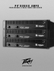
® PV SERIES AMPS PROFESSIONAL STEREO POWER AMPLIFIERS O P E R AT I N G G U I D E
Intended to alert the user to the presence of uninsulated “dangerous voltage” within the product’s enclosure that may be of sufficient magnitude to constitute a risk of electric shock to persons. Intended to alert the user of the presence of important operating and maintenance (servicing) instructions in the literature accompanying the product. CAUTION: Risk of electrical shock — DO NOT OPEN! CAUTION: To reduce the risk of electric shock, do not remove cover. No user serviceable parts inside.
IMPORTANT SAFETY INSTRUCTIONS WARNING: When using electrical products, basic cautions should always be followed, including the following: 1. 2. 3. 4. 5. 6. 7. 8. 9. 10. 11. 12. 13. 14. 15. 16. 17. Read these instructions. Keep these instructions. Heed all warnings. Follow all instructions. Do not use this apparatus near water. Clean only with a dry cloth. Do not block any of the ventilation openings. Install in accordance with manufacturer’s instructions.
ENGLISH PV® SERIES PROFESSIONAL STEREO POWER AMPLIFIER INTRODUCTION Congratulations! You have just purchased the world’s finest professional power amplifier. The PV amplifier features a two-way crossover and sub-sonic (low-cut) filter for each channel. Crossover frequencies are fixed at 150 Hz, allowing subwoofers to be driven at extremely high sound pressure levels, and the filters cut at 40 Hz to prevent low-end rumble.
FRONT PANEL FEATURES 1 5 23 4 432 1 (1) INPUT GAIN (dB) These controls are used to adjust the input gain of each channel. They determine how “loud” each channel of the power amplifier will sound for a given input signal level. Maximum input gain is achieved at the fully clockwise setting (+32 dB, 40 X), and this setting yields maximum mixer/system headroom. A setting of less than fully clockwise will yield lower system noise at the expense of mixer/system headroom.
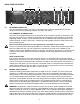
BACK PANEL FEATURES 6 7 (7) 9 10 8 11 15 18 12 17 14 16 13 IEC MAINS CONNECTOR This is a standard IEC power connector. An AC mains cord having the appropriate AC plug and ratings for the intended operating voltage is included in the carton. U.S. DOMESTIC AC MAINS CORD The mains cord supplied with the unit is a heavy-duty, three-conductor type with a conventional 120 VAC plug with ground pin. It should be connected to an independent circuit capable of continuously supporting at least 15 amps.
(9) SPEAKON® OUTPUTS PV® amplifiers utilize three 4-conductor Speakon connectors, one for each channel and one for BRIDGE mode. Please refer to the BRIDGE MODE section of this manual before attempting to use this mode. For each channel Speakon, the same impedance rules apply as with the binding posts. Internally, all the Speakons are wired in what is called the “high current” mode, with pins 1+ and 2+ in parallel, and pins 1- and 2- in parallel.
when relatively short 1/4" cable patches are made to this input from various outputs on this amplifier, or from other equipment that shares the same rack with this amplifier. The quasi-balanced circuitry is “automatic” and virtually “invisible” in normal usage. This feature can be defeated with a jumper on the barrier strip from the “-” input terminal of that channel to the ground terminal. (15) LOW CUT SWITCH This switch is used to activate the LOW CUT filter for the corresponding channel.
high-power operating levels occur. Then, as temperatures in the amplifier heat sinks increase, the automatic thermal-sensing circuitry will cause high-speed operation to occur. Depending upon signal conditions and amp loading, high-speed fan operation may continue or the fan may cycle continuously between high and low. This situation is quite normal.
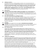
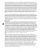
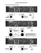
AMPLIFIER CONFIGURATIONS BASIC FULL-RANGE STEREO SYSTEM Left Full-Range Speaker(s) Right Full-Range Speaker(s) L&R THRU Outputs L&R Inputs MONO BI-AMPED SYSTEM 1 2 1 2 1/4" Tip/Sleeve Patch Cord Mono Input Full-Range Speaker(s) Sub Speaker(s) Push-Push Switch Activation List: 1 - Chan A Low Cut Switch IN 2 - Chan A 150 Hz Xover Switch IN PARALLEL (MONO) MODE THRU Outputs Full-Range Speaker(s) Full-Range Speaker(s) 10 1/4" Tip/Sleeve Patch Cord Mono Input
STEREO BI-AMPED SYSTEM 1 2 3 4 1/4" Tip/Sleeve Patch Cords Right Full-Range Speaker(s) Left Full-Range Speaker(s) Right Sub Speaker(s) L&R Inputs Left Sub Speaker(s) Push-Push Switch Activation List: 1 - Chan A Low Cut Switch IN 2 - Chan A 150 Hz Xover Switch IN 3 - Chan B Low Cut Switch IN 4 - Chan B 150 Hz Xover Switch IN BRIDGE CONFIGURATION 1 2 Sub Speaker(s) Mono Input Push-Push Switch Activation List: 1 - Chan A, Low Cut Switch IN 2 - Mode Switch IN (Bridge) 10 11
Specifications PV® 900 PV® 1500 PV® 2600 RATED OUTPUT POWER: Stereo mode (EIA both channels driven) 4 Ohms EIA, 1 kHz, 1% THD 8 Ohms EIA, 1 kHz, 1% THD Bridge mode, mono 8 Ohms EIA, 1 kHz, 1% THD 300 W RMS/chan 180 W RMS/chan 500 W RMS/chan 300 W RMS/chan 900 W RMS/chan 550 W RMS/chan 600 W RMS 1000 W RMS 1800 W RMS HUM & NOISE: Stereo mode, below rated output power, 4 ohms 100 dB, unweighted 100 dB, unweighted 100 dB, unweighted DISTORTION: SMPTE-IM Less than 0.01% Less than 0.
FRANÇAIS AMPLIFICATEURS PROFFESSIONNELS STEREO PV® SERIES INTRODUCTION Félicitations pour avoir choisi l’un des meilleurs amplificateurs de puissance! Les unités de la série PV possèdent toutes un filtre actif 2-voies et un filtre coupe-bas sub-sonique sur chaque canal. La fréquence du filtre actif est fixée à 150 Hz, idéale pour piloter un caisson basses fréquences et celle du filtre coupe-bas est à 40 Hz pour éviter tout dommage à vos hauts-parleurs.
PANNEAU AVANT 1 5 23 4 432 1 (1) GAIN D’ENTREE(dB) Ces contrôles vous permettent d’ajuster le niveau d’entrée de chaque canal. Ils déterminent la ‘puissance’ du canal correspondant pour un signal d’entrée donné. Le gain augmente quand vous tournez horairement ce contrôle. Positionnez ces contrôles en position minimum (sens contre horaire) pour les mises sous et hors tension dans le but de protéger vos hauts-parleurs.
PANNEAU ARRIERE 6 7 (7) 9 10 8 11 15 18 12 17 14 16 13 CONNECTEUR IEC Ce connecteur standard IEC vous permet d’alimenter votre unité. Un cable de connexion IEC est fourni avec votre unité pour permettre de le relier à votre source électrique (prise murale). Ne jamais déconnecter la connexion de terre de votre unité. L’utilisation de rallonge est à éviter mais, si nécessaire, utilisez un cable et connecteur 3-conducteurs de 2.5 mm2 de section minimum.
(11) SELECTEUR DDT™ (DISTORTION DETECTION TECHNIQUE) Ce sélecteur vous permet d’enclencher ou non la compression DDT. Vous pouvez changer sa position avec un outil approprié (Sélecteur de type ‘pousse-pousse). La position enfoncée garde la compression inactive, la position sortie active. Nous vous conseillons de garder enclenchée la compression DDT pour éviter qu’un ou les deux canaux ne clippent ou se mettent en surcharge.
envoyé vers le canal correspondant sans être affecté par ce filtre. La fréquence de ce filtre est fixée à 150 Hz et ne peut être changée. Il utilise l’approximation Linkwitz-Riley en configuration 4-poles. (17) SORTIES JACKS THRU/LOW Comme détaillé dans le paragraphe ‘SELECTEUR DE FILTRE’(15), ce jack 1/4" vous permet de récupérer les fréquences graves (inférieures à 150 Hz) de votre signal à l’entrée du canal si le filtre actif est activé.
MODE PONT (BRIDGE) Le mode pont est souvent mal compris. Il s’agit d’utiliser les deux cotés de votre unité comme un seul amplificateur dont la puissance est l’addition des puissances de ces canaux et dont la charge minimum de travail est l’addition des charges minimum de ces canaux. Par exemple, le PV1500 est donné à 750 Watts RMS par canal sous 2 Ohms. Le mode pont donnera cette unité à 1500 Watts RMS sous 4 Ohms (charge minimum).
Specifications PV® 900 PV® 1500 PV® 2600 450 W RMS/chan 300 W RMS/chan 180 W RMS/chan 750 W RMS/chan 500 W RMS/chan 300 W RMS/chan 1300 W RMS/chan 800 W RMS/chan 540 W RMS/chan 900 W RMS 600 W RMS 1500 W RMS 1000 W RMS 2600 W RMS 1800 W RMS HUM & NOISE: Stereo mode, below rated output power, 4 ohms 100 dB, unweighted 100 dB, unweighted 100 dB, unweighted DISTORTION: SMPTE-IM Less than 0.01% Less than 0.01% Less than 0.
DEUTSCH SERIE DE AMPLIFICADORES PROFESIONALES ESTÉREO PV® INTRODUCCIÓN ¡Felicidades! Acabas de comprar el mejor amplificador profesional del mundo. El amplificador PV incluye un crossover de 2 vías y filtro sub-sonoro (corte de graves) para cada canal. La frecuencia del crossover es 150 Hz permitiendo que los subwoofers sean capaces de generar altos niveles de presión sonora, mientras que los filtros cortan en 40 Hz para prevenir distorsiones graves.
FUNCIONES DEL PANEL FRONTAL 1 23 4 432 1 5 (1) GANANACIA DE ENTRADA (dB) Estos controles son usados para ajustar la ganancia de cada canal. Determinan lo "fuerte" que estará cada canal del amplificador con un nivel de entrada dado. La ganancia máxima de entrada se consigue en la posición completamente en dirección de las manecillas del reloj (+32 dB, 40X), y esta posición también da máximo umbral entre la mezcladora/sistema.
FUNCIONES DEL PANEL TRASERO 6 9 7 (7) 8 10 11 15 18 12 17 14 16 13 CONECTOR PARA CABLE DE CORRIENTE IEC Este es para un conectador estándar IEC. Se incluye en el paquete un cable de corriente con las especificaciones necesarias de voltaje para la operación. CABLE DE CORRIENTE DOMESTICO PARA EE.UU El cable de corriente incluido con la unidad es de nivel industrial de 3 conductores con un conectador convencional de 120 VAC con aguja de tierra.
(11) INTERRUPTOR DDT™ (TÉCNICA DE DETECCIÓN DE DISTORSIÓN) Este interruptor se usa para encender o apagar los circuitos de compresión DDT. También es un interruptor convencional de oprimir que requiere una pequeña ‘herramineta’ para ser activado. La posición DENTRO es APAGADO, la posición FUERA es ACTIVO. Normalmente, la función DDT debe estar activada para reducir la posibilidad de que uno o ambos canales saturen.
Cuando el interruptor esté en la posición DENTRO, las señales de entrada son mandadas por el crossover, y las frecuencias graves son mandadas automáticamente al canal correspondiente. Al mismo tiempo, las frecuencias agudas son mandadas a la SALIDA DE AGUDOS (18) y deben ser conectadas a la ENTRADA del otro canal de este amplificador o entrada de otro amplificador para completar el sistema bi-amplificado.
MODO PUENTE El modo puente en amplificadores estéreo es comúnmente incomprendido en lo que refiere a su operación y uso. En términos básicos, cuando un amplificador de 2 canales se opera en modo Puente, se convierte en una unidad de un solo canal con una capacidad igual a la suma de los canales independientes, con una carga del doble del de un canal independiente. Por ejemplo, el PV 1500 cuenta con 750 Watts RMS por canal a 2 Ohmios. En modo Puente será de 1500 Watts a 4 ohmios (carga mínima).
NOTES: 26
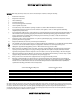
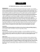
PEAVEY ELECTRONICS CORPORATION LIMITED WARRANTY Effective Date: July 1, 1998 What This Warranty Covers Your Peavey Warranty covers defects in material and workmanship in Peavey products purchased and serviced in the U.S.A. and Canada.
Features and specifications are subject to change without notice. Peavey Electronics Corporation • 711 A Street • Meridian, MS 39301 (601) 483-5365 • Fax (601) 486-1278 • www.peavey.