Q™ Series Operation Manual For more information on other great Peavey products, go to your local Peavey dealer or online at www.peavey.com.
Intended to alert the user to the presence of uninsulated “dangerous voltage” within the product’s enclosure that may be of sufficient magnitude to constitute a risk of electric shock to persons. Intended to alert the user of the presence of important operating and maintenance (servicing) instructions in the literature accompanying the product. CAUTION: Risk of electrical shock — DO NOT OPEN! CAUTION: To reduce the risk of electric shock, do not remove cover. No user serviceable parts inside.
IMPORTANT SAFETY INSTRUCTIONS WARNING: When using electrical products, basic cautions should always be followed, including the following: 1. 2. 3. 4. 5. 6. 7. 8. 9. 10. 11. 12. 13. 14. 15. 16. 17. 18. Read these instructions. Keep these instructions. Heed all warnings. Follow all instructions. Do not use this apparatus near water. Clean only with a dry cloth. Do not block any of the ventilation openings. Install in accordance with manufacturer’s instructions.
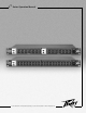
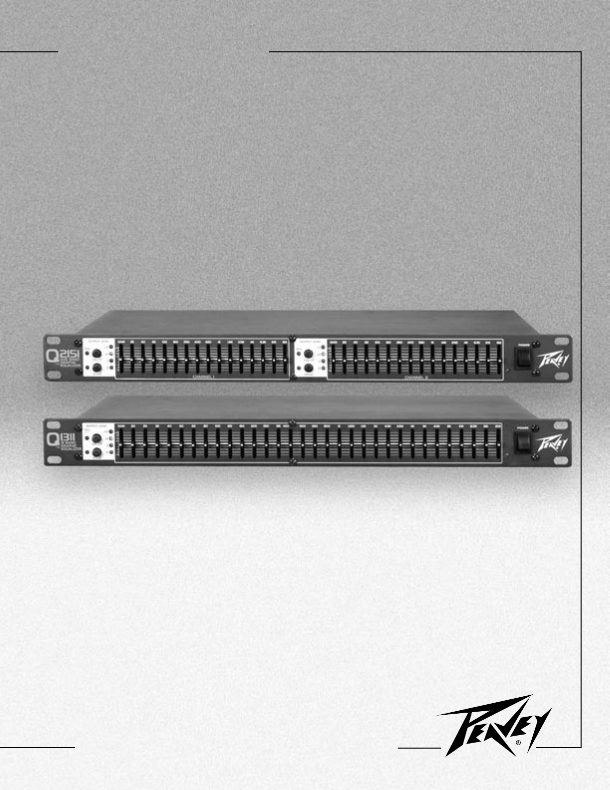
ENGLISH Q™ SERIES EQUALIZERS Thank you for purchasing a Peavey Electronics Q Series graphic equalizer. The Q family features one dual-channel model (Q2151) and one single-channel model (Q1311), both incorporating Peavey’s legendary low noise, low distortion design. These ruggedly constructed Q Series EQs have 20 mm, center-detented control sliders enclosed in metal for durability.
EQUALIZATION PROCESS Always begin the equalization process with all sliders at their center-detent (flat response) positions. Lower each fader until the feedback frequency is found. Lower the faders in small amounts to avoid adversely affecting sound quality. Likewise, excessive boosting of a frequency may result in feedback. EXERCISE CAUTION WHEN ATTEMPTING TO BOOST FREQUENCIES BELOW SPEAKER SYSTEM TRANSDUCER CUT-OFF.
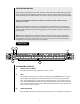
frequency bands. They are adjustable within ±12 dB, or ±6dB for improved precision. (4) LOW CUT FILTER This switch activates the low cut filter, which rejects frequencies below 40 Hz. Frequency rolloff is 24 dB per octave with the switch engaged. This filter will operate even with the BYPASS (5) switch engaged. The adjacent red LED indicates activation.
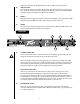
(9) XLR OUTPUT These three-pin male connectors provide balanced output when used with female XLR connectors. (10) TRS BALANCED INPUT These 1/4" tip/ring/sleeve (stereo) jacks provide balanced input when used with TRS connectors and two-conductor shielded cables. When used with mono 1/4" (TS) phone plugs, the input is unbalanced. (11) XLR INPUT These three-pin female connectors provide balanced input when used with male XLR connectors.
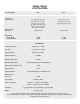
Q2151/Q1311 SPECIFICATIONS SPECIFICATIONS* Filter Q Filter Center Frequencies, Hz Maximum Filter Boost/Cut Output Noise Bypass Mode Filter (Flat) Mode Q1311 Q2151 4.77 2.3 20, 25, 32, 40, 50, 63, 80 100, 125, 160, 200, 250, 315, 400, 500, 630, 800, 1 k, 1.25 k, 1.6 k, 2 k, 2.5 k, 3.15 k, 4 k, 5 k, 6.3 k, 8 k, 10 k, 12.5 k, 16 k, 20 k 25, 40, 63, 100, 160, 250, 400, 630, 1 k, 1.6 k 2.5 k, 4 k, 6.
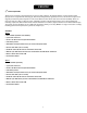
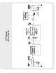
BLOCK DIAGRAM Q™ Series
PEAVEY ELECTRONICS CORPORATION LIMITED WARRANTY Effective Date: July 1, 1998 What This Warranty Covers Your Peavey Warranty covers defects in material and workmanship in Peavey products purchased and serviced in the U.S.A. and Canada.
Features and specifications subject to change without notice. Peavey Electronics Corporation • 711 A Street • Meridian, MS 39301 (601) 483-5365 • FAX (601) 486-1278 • www.peavey.com ©2002 Printed in the U.S.A.