™ Q Series Graphic Equalizers SERIES Q215B QF215 QF131 O P E R AT I N G M A N U A L
Intended to alert the user to the presence of uninsulated “dangerous voltage” within the product’s enclosure that may be of sufficient magnitude to constitute a risk of electric shock to persons. Intended to alert the user of the presence of important operating and maintenance (servicing) instructions in the literature accompanying the product. CAUTION: Risk of electrical shock — DO NOT OPEN! CAUTION: To reduce the risk of electric shock, do not remove cover. No user serviceable parts inside.
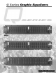
ENGLISH Q™ SERIES EQUALIZERS Thank you for purchasing a Peavey Electronics Q Series graphic equalizer. The Q family features two dual-channel models and one single-channel unit, all incorporating Peavey’s legendary lownoise, low-distortion design. Ruggedly constructed, Q Series EQs have 45 mm, center-detented control sliders enclosed in metal for durability. These two rack-space units also offer ±15 dB gain control and an LED display indicating output level.
EQUALIZATION PROCESS Always begin the equalization process with all sliders at their center-detent (flat response) positions. For units equipped with FLS®, increase system volume until slight feedback occurs. Note the LED(s) that illuminate, and lower the corresponding fader(s) until feedback is eliminated. In other words, see the light pull down the fader. For the Q 215B, lower each fader until the feedback frequency is found. Lower the faders in small amounts to avoid adversely affecting sound quality.
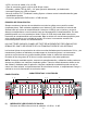
(3) EQUALIZER SECTION These calibrated, detented controls adjust the amount of cut or boost at their respective frequencies. They are adjustable from 18 dB cut to 12 dB boost (15 dB cut to 15 dB boost on the 215B). For units equipped with FLS, the LED at the top of each band will illuminate as an indication of feedback at that frequency. (4) LOW-CUT FILTER This switch activates the low-cut filter that rejects frequencies below 40 Hz. Frequency roll off is 18 dB per octave with the switch engaged.
(8) TRS BALANCED OUTPUT These 1/4" Tip/Ring/Sleeve (stereo) jacks provide balanced output when used with TRS connectors and 2-conductor shielded cables. When used with a mono 1/4" (TS) phone plug, the output is unbalanced. (9) XLR OUTPUT These male 3-pin connectors provide balanced output when used with female XLR connectors. (10) TRS BALANCED INPUT These1/4" Tip/Ring/Sleeve (stereo) jacks provide balanced input when used with TRS connectors and 2-conductor shielded cables.
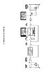
Q™ SERIES BLOCK DIAGRAM
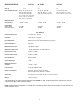
SPECIFICATIONS* Filter Q Filter Frequencies (Hz) Maximum Boost and Cut Filter Output Noise Bypass Mode Filter Mode (Flat) Q™F131 4.77 20, 25, 32, 40, 50, 63, 80, 100, 125, 160, 200, 250, 315, 400, 500, 630, 800, 1 K, 1.25 K, 1.6 K, 2 K, 2.5 K, 3.15 K, 4 K, 5 K, 6.3 K, 8 K, 10 K, 12.5 K, 16 K, 20 K +12 dB / -18 dB -101 dBV -95 dBV Q™ 215B Q™F215 2.3 2.3 25, 40, 63, 100, 160 250, 400, 630, 1 K, 1.6 K, 2.5K, 4 K, 6.3K, 10 K, 16 K 25, 40, 63, 100, 160, 250, 400, 630, 1 K, 1.6 K, 2.5 K, 4 K, 6.
ESPAÑOL ECUALIZADORES Q™ SERIES Gracias por su compra de un ecualizador gráfico serie Q de Peavey. La familia Q es caracterizada por dos modelos de canales dobles y unidades de un solo canal, todas incorporando el diseño legendario de Peavey de bajo ruido y baja distorsión. Construidos fuertemente, los ecualizadores de la serie Q de Peavey cuentan con sliders con punto de detención medio de 45 mm incrustados en metal para durabilidad.
• • • • • LEDs de nivel de salida(-12 a +12 dB) Filtro de recorte de graves a 40 Hz de18 dB por octava Entradas y salidas TRS de XLR y 1/4" para operación balaceada y no balanceada Interruptor Bypass con LED de estatus Nuevos circuitos FLS® (Feedback Locating System –sistema contra la retroalimentación) para sensibilidad mejorada • Control de ganancia de15 dB recorte / 15 dB aumento PROCESO DE ECUALIZACIÓN Siempre comienza el proceso de ecualización con todos los sliders en su posición central (respuesta p
(2) GANANCIA Este control calibrado regula la ganancia general de la SECCIÓN DEL ECUALIZADOR (3). La ganancia unitaria a través de la cadena de la señal se puede mantener recuperando la ganancia de la señal en este punto. El proceso de ecualización puede dar como resultado pérdida de señal perceptible. Para compensar esta pérdida, activa el interruptor de BYPASS (5) y compara el nivel de la señal con el nivel del ecualizador.
Nunca se rompa el tercer contacto de tierra de ningún aparato. Este ha sido incluido por seguridad. Si la fuente de corriente no cuenta con una conexión de tierra, se debe utilizar un adaptador con tierra y el tercer contacto debe ser aterrizado propiamente. Para prevenir el riesgo de toques eléctricos o fuego, siempre hay que asegurarse que el ecualizador y todo el equipo con él asociado está propiamente aterrizado.
ESPECIFICACIONES* Q™F131 Q™ 215B Q™F215 Filtro Q 4.77 2.3 2.3 Frecuencias filtradas (Hz) 20, 25, 32, 40, 50, 63, 80, 100, 125, 160, 200, 250, 315, 400, 500, 630, 800, 1 K, 1.25 K, 1.6 K, 2 K, 2.5 K, 3.15 K, 4 K, 5 K, 6.3 K, 8 K, 10 K, 12.5 K, 16 K, 20 K Incremento máximo y filtros de recort Ruido de salida Modo Bypass Modo Filtrado (Plano) +12 dB / -18 dB -101 dBV -95 dBV 25, 40, 63, 100, 160 250, 400, 630, 1 K, 1.6 K, 2.5K, 4 K, 6.3K, 10 K, 16 K 25, 40, 63, 100, 160, 250, 400, 630, 1 K, 1.
INSTRUCCIONES DE SEGURIDAD IMPORTANTES ADVERTENCIA: Al utilizar productos eléctricos se deben respetar las precauciones básicas, que incluyen las siguientes: 1. Lea estas instrucciones. 2. Conserve estas instrucciones. 3. Preste atención a todas las advertencias. 4. Respete todas las instrucciones. 5. No utilice este aparato cerca del agua. Por ejemplo, cerca o dentro de bañeras, piscinas, lavaderos, sótanos húmedos, etc. 6. Limpie el aparato solamente con un trapo húmedo. 7.
FRANÇAIS EQUALISEURS Q™ SERIES Merci d’avoir choisi un équaliseur graphique Q Series de Peavey Electronics. Il est mono ou double canal (suivant les modéles), au standard Rack 2-unités et possède des curseurs de 45 mm à chassis métal pour la fiabilité.
PROCEDURE D’EQUALISATION Toujours commencer avec tous les curseurs dans leur position centrale (0). Pour les unités équippées du FLS®, augmentez le volume de votre système pour obtenir une légère boucle de son (Feedback). Notez la Led illuminée, puis diminuez la valeur du curseur correspondant jusqu’à la disparition de la boucle. En d’autres mots: Localisez la Led, baissez le curseur correspondant. Pour le Q215B, baisser chaque curseur jusqu’à localiser la fréquence de boucle.
(3) SECTION EQUALISATION Ces curseurs calibrés vous permettent de controler la valeur (+ou-) d’altération de la fréquence correspondante. Ils sont ajustables de -18 dB à +12 dB (-15 dB à +15 dB pour le 215B). Pour les modèles équippés du FLS, la Led située au sommet des curseurs s’illuminera pour indiquer la fréquence de départ d’une éventuelle boucle de son. (4) FILTRE COUPE-BAS Ce sélecteur active le filtre coupe-bas qui bloque les fréquences inférieures à 40 Hz.
(8) SORTIE TRS Ces jacks 1/4" TRS (3-connecteurs) vous permettent de récupérer un signal symétrique si utilisé avec un cable à fiche 3-connecteurs (Stéréo). Le signal sera assymétrique avec une fiche 2-connecteurs (Mono). (9) SORTIE XLR Ces sorties XLR 3-connecteurs permettent de récupérer un signal symétrique en utilisant une fiche femelle XLR.
SPECIFICATIONS* Q™F131 Q™ 215B Q™F215 Filter Q 4.77 2.3 2.3 25, 40, 63, 100, 160 250, 400, 630, 1 K, 1.6 K, 2.5K, 4 K, 6.3K, 10 K, 16 K 25, 40, 63, 100, 160, 250, 400, 630, 1 K, 1.6 K, 2.5 K, 4 K, 6.3 K, 10 K, 16 K +15 dB / -15 dB +12 dB / -18 dB -100 dBV -98 dBV -100 dBV -98 dBV Filter Frequencies (Hz) Maximum Boost and Cut Filter Output Noise Bypass Mode Filter Mode (Flat) 20, 25, 32, 40, 50, 63, 80, 100, 125, 160, 200, 250, 315, 400, 500, 630, 800, 1 K, 1.25 K, 1.6 K, 2 K, 2.5 K, 3.
NOTE IMPORTANTE CONCERNANT LA SECURITE ATTENTION: Lors de l’utilisation de appareils électriques, certaines mesures de sécurité doivent être respectées: 1. Lisez toutes les instructions. 2. Conservez ces instructions. 3. Tenez compte de tous les avertissements. 4. Suivez précisemment les instructions. 5. N’utilisez pas l’appareil à proximité de l’eau. Par exemple prés d’un bain, d’une piscine, d’un évier, ou dans un sous-sol humide. 6. Nettoyez avec un chiffon sec uniquement. 7.
DEUTSCH Q™ SERIES EQUALIZERS Wir freuen uns, dass Sie sich für einen graphischen Equalizer der Peavey Electronics Q Series entschieden haben. Die Q-Familie umfasst zwei zweikanalige sowie ein einkanaliges EqualizerModell in der bekannt rausch- und verzerrungsarmen Peavey-Qualität. Für einen störungsfreien Betrieb sind die robusten EQs der Q Series mit metallgekapselten 45-mm-Slidern mit gerasteter Mittelposition ausgestattet.
• Ausgangspegel-LED-Anzeige (-12 to +12 dB) • Low-Cut-Filter mit Status-LED (40 Hz, 18 dB pro Oktave) • Eingänge und Ausgänge als 6,3-mm-Stereoklinke und XLR für symmetrischen oder unsymmetrischen Betrieb • Bypass-Schalter mit Status-LED • Neu entwickelte FLS-Schaltung (Feedback Locating System) für höhere Eingangsempfindlichkeit • Gain-Regler mit 15 dB Anhebung / 15 dB Absenkung EINSATZ DES EQUALIZERS Möchten Sie ein Signal entzerren, d.h.
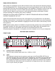
FUNKTIONEN UND REGLER GERÄTEFRONT 1 4 5 2 3 1 2 3 4 5 6 (1) OUTPUT LEVEL-LED-ANZEIGE Diese LED-Anzeige dient der Anzeige des Ausgangspegels (–12 dB ... +12 dB). (2) GAIN Mit diesem speziell kalibrierten Regler mit Mittelrastung steuern Sie die Eingangsverstärkung der gesamten EQUALIZER-Sektion (3). Den Arbeitspegel von 0 dB (“Unity Gain”) stellen Sie sicher, in dem Sie die im Verlauf der Signalkette möglicherweise eingebüßte Verstärkung hier wieder aufholen.
RÜCKSEITE TM F 215 CAUTION MOUNT IN RACK ONLY INSTALLER SUR SUPPORT DE MONTAGE SEULEMENT 215 2 x 15 BAND PROFESSIONAL GRAPHIC EQUALIZER CAUTION: TO REDUCE THE RISK OF FIRE OR ELECTRIC SHOCK DO NOT EXPOSE THIS EQUIPMENT TO RAIN OR MOISTURE. AVIS:RISQUE DE CHOC ELECTRIQUE-NE PAS OUVRIR. 230V 50/60 Hz 12 WATTS 7 (7) A PRODUCT OF PEAVEY ELECTRONICS CORP. MERIDIAN, MS DESIGNED IN U.S.A.
TECHNISCHE DATEN* Q™F131 Q™ 215B Q™F215 Q-Faktor 4.77 2.3 2.3 Filter-Frequenzen (Hz) Max. Anhebung und Absenkung (Filter) 20, 25, 32, 40, 50, 63, 80, 100, 125, 160, 200, 250, 315, 400, 500, 630, 800, 1 K, 1.25 K, 1.6 K, 2 K, 2.5 K, 3.15 K, 4 K, 5 K, 6.3 K, 8 K, 10 K, 12.5 K, 16 K, 20 K +12 dB / -18 dB Rauschverhalten (Ausgang) Bypass-Betrieb -101 dBV Filter-Betrieb (linear) -95 dBV 25, 40, 63, 100, 160 250, 400, 630, 1 K, 1.6 K, 2.5K, 4 K, 6.
WICHTIGE SICHERHEITSRICHTLINIEN WARNUNG: Beim Einsatz elektrischer Geräte sollten stets nachfolgend genannte grundlegende Sicherheitsrichtlinien beachtet werden: 1. Lesen Sie diese Richtlinien. 2. Bewahren Sie diese Richtlinien stehts griffbereit auf. 3. Beachten Sie sämtliche Richtlinien. 4. Befolgen Sie alle Anweisungen. 5. Benutzen Sie das Gerät nicht in unmittelbarer Wassernähe (z. B. Badewanne, Waschbecken, Swimming-Pool, etc.). 6. Nur mit einem feuchten oder klammen Tuch reinigen. 7.
PEAVEY ELECTRONICS CORPORATION LIMITED WARRANTY Effective Date: July 1, 1998 What This Warranty Covers Your Peavey Warranty covers defects in material and workmanship in Peavey products purchased and serviced in the U.S.A. and Canada.
IMPORTANT SAFETY INSTRUCTIONS WARNING: When using electric products, basic cautions should always be followed, including the following: 1. 2. 3. 4. 5. 6. 7. 8. 9. 10. 11. 12. 13. 14. 15. 16. 17. 18. Read all safety and operating instructions before using this product. All safety and operating instructions should be retained for future reference. Obey all cautions in the operating instructions and on the back of the unit. All operating instructions should be followed.