OPERATING GUIDE
Intended to alert the user to the presence of uninsulated “dangerous voltage” within the product’s enclosure that may be of sufficient magnitude to constitute a risk of electric shock to persons. Intended to alert the user of the presence of important operating and maintenance (servicing) instructions in the literature accompanying the product. CAUTION: Risk of electrical shock — DO NOT OPEN! CAUTION: To reduce the risk of electric shock, do not remove cover. No user serviceable parts inside.
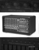
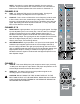
ENGLISH XR® 696 POWERED SOUND REINFORCEMENT MIXING CONSOLE Representing years of research and development in mixer engineering, the XR 696 is a state-of-theart powered mixer packed with features. Incorporating DSP-based reverb/effects and delivering an awesome output of 600 Watts per channel program material (@ 4 Ohms), this compact, lightweight mixer is perfect for most any application. Designed for durability and ease of operation, the XR 696 will provide years of hassle-free performance.
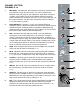
CHANNEL SECTION: CHANNELS 1-4 1. 2. 3. 4. 5. 6. 7. 1 5 MIC INPUT: XLR balanced, low-impedance channel input optimized for a microphone or other low-level source. Pin 2 is the positive input. Because of the wide range of gain adjustment, signal levels as high as +10 dBV (2.45 V RMS) can be accommodated. When the phantom power is enabled, this connector has +48 V on pins 2 and 3 with pin 1 as the ground reference. (The Mic Input can also be found on Channels 5 - 8.) See caution on page 7.
NOTE: Channels 5-9 contain features that differ from the previous channels. Only those features are mentioned below. For information on features not mentioned please refer to the section for Channels 1-4. 6 5 CHANNELS 5-6 0 10. LINE: 1/4" balanced TRS input for line-level signals. This signal is connected through a 25 dB pad to the mic input below it. 11.
MASTER SECTION 16. EFFECTS PEAK LED: Illuminates to indicate -6 dB of headroom before the signals being sent to the effects circuit are clipped. Ideally, you would want this LED to light only occassionally. An occassional blink indicates that you have the levels at an optimum setting. It is advisable to listen carefully to the output at the same time in order to determine the final setting. 17. PRESET: Selects the effect preset from the list below.
17 ESET 16 15 1 5 5 20 7 9 0 PRESET 5 0 10 10 5 0 125 63 10 10 0 EFX. TO MON. COLOR/TONE TIME/SIZE SENDS DIGITAL EFFECTS FLS 22 21 5 11 PEAK (-6dB) 19 3 13 S 18 EFX.
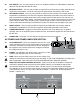
28. EFX DEFEAT: This 1/4" jack accepts an on/off 1/4" footswitch (Peavey Pt. #00051000) to defeat the effects of both the Main and Monitor mixes. 29. MONITOR OUTPUT: This 1/4" jack provides an output from the monitor mix to supply external power amp/monitor combinations. The level of this signal is determined by the Monitor Level control. 30. LEFT/MONO OUTPUT: This 1/4" jack provides an output from the Left Main mix to supply external amp/speaker combinations.
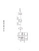
PAD PAD TAPE/CD INPUT CHANNEL GAIN LO M I D HI EFX LEVEL TONE CONTROL LO HI Mon Send LO M I D HI CHANNEL GAIN LO M I D HI LO HI EFX LEVEL TONE CONTROL MONITOR SEND Monitor Send EFX LEVEL TONE CONTROL CHANNEL GAIN MIC PREAMP CHANNEL 9 (TAPE) LO-Z INPUT +48V Phantom RIGHT LEFT/ MONO STEREO LINE INPUT CHANNEL GAIN LO MIDHI TONE CONTROL MONITOR SEND MIC PREAMP CHANNELS 7-8 LO-Z INPUT +48V Phantom LINE INPUT CHANNELS 5-6 LO-Z INPUT +48V Phantom MIC PREAMP CHANNELS 1-4 HI
LO-Z MIC (NO PAD) HI-Z (W/PAD) HI-Z MIC (NO PAD) LO-Z MIC (W/PAD) LINE/TAPE INPUTS -60 -50 -40 -30 -20 -10 0 dBu +10 +20 +30 -60 dBu -28 dBu -35 dBu -12.5 dBu -11 dBu +13.5 dBu +21 dBu +2 dBu = 0 dBV EQ -15 dB +15 dB LEFT & RIGHT OUT +21 dBu MAX -10 dBu NOM.
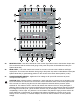
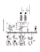
XR® 696 In - Left/Right Mode Mains - Left Mains - Right Impulse® 1012 ® Impulse 1012 Left/Monitor Outputs (Rear) LOW CUT 1 2 5 0 0 10 EFX. 0 80Hz CHANNELS 1-6 ONLY 5 0 10 EFX. 0 5 0 10 EFX. 0 6 5 4 3 5 Right/Main Outputs (Rear) 5 0 10 EFX. 0 7 low cut 5 0 10 EFX. 0 8 STEREO 5 0 10 EFX. 0 STEREO 5 0 10 EFX. PRESET 1-7 REVERBS 8 DELAY + REVERB 9-12 DELAYS 13-15 MODULATIONS 16 ROTARY SPEAKER 10 EFX.
XR® 696 In Monitor/Main Mode Mains Impulse® 1012 Monitors SP™ 112MX Left/Monitor Outputs (Rear) LOW CUT 1 2 5 0 0 10 EFX. 0 80Hz CHANNELS 1-6 ONLY 5 0 10 EFX. 0 5 0 10 EFX. 0 6 5 4 3 5 Right/Main Outputs (Rear) 5 0 10 EFX. 0 7 low cut 5 0 10 EFX. 0 8 STEREO 5 5 0 10 EFX. 0 STEREO 0 10 EFX. 0 PRESET 1-7 REVERBS 8 DELAY + REVERB 9-12 DELAYS 13-15 MODULATIONS 16 ROTARY SPEAKER 10 EFX.
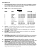
XR® 696 SPECIFICATIONS: Input Specifications: Function Input Z (Ohms) Min Lo-Z (150 Ohms) 2k Channels 1-8 Hi-Z 100 k Channels 1-4 Line Input 22 k Channels 5-8 Tape Channel 9 20 k Input Gains Control Setting Min** Input Levels Nominal* Max Max w/o pad (50 dB) -60 dBu -30 dBu -11 dBu Max. w/ pad (25 dB) -35 dBu -5 dBu +13.5 dBu Max w/o pad (50 dB) -60 dBu -30 dBu -12 dBu Max w/ pad (25 dB) -35 dBu -5 dBu Max. w/o pad (30 dB) Max.
Frequency Response: Mic Input to L - R Output Line Input to L - R Output To Power Amplifier Output 20 Hz - 20 kHz +0 dB/-1 dB 20 Hz - 20 kHz +0 dB/-1 dB 20 Hz - 20 kHz +0 dB/-1 dB Total Harmonic Distortion (THD): < 0.01% 20 Hz - 20 kHz mic input to L/R Mon. output at nominal level (20 Hz - 80 kHz BW) < 0.01% 20 Hz - 20 kHz line input to L/R output at output at nominal level (20 Hz - 80 kHz BW) < .
XR® 696/1200 SC AMPLIFIER SPECIFICATIONS POWER SECTION (1200 SC Module with DDT™) Hum and Noise: -97 dB below 500 Watts Frequency Response: +0, -1 dB, 20 Hz - 20 kHz @ rated power Damping Factor: Greater than 100 @ 1 kHz, 4 Ohms Rated Power: • 600 Watts program into 4 Ohms, both channels driven / 500 Watts RMS into 4 Ohms, both channels driven • 475 Watts program into 8 Ohms, both channels driven / 360 Watts RMS into 8 Ohms, both channels driven Input Sensitivity: 2.
ESPAÑOL CONSOLA DE MEZCLA PARA REPRODUCCIÓN DE SONIDO CON PODER XR® 696 Representando años de construcción e investigación en ingeniería de consolas, la XR 696 es una consola con poder del más alto nivel. Incorporando procesadores de reverberación y otros efectos basados en DSP (Proceso de señal digital, por sus siglas en inglés) y sorprendente salida de 600 watts por canal (@ 4 ohmios), esta consola compacta y de bajo peso es perfecta para casi cualquier aplicación.
SECCIÓN DE CANALES CANALES 1-4 1. 2. 3. 4. 5. 1 ENTRADA DE MICRÓFONO: Entrada de baja impedancia, XLR, balanceada optimizada para micrófonos u otra fuentes de bajo nivel. La aguja 2 es la entrada positiva. Dado el amplio rango de ajustes de ganancia, se pueden usar señales de hasta +10 dBV (2.45 V RMS). Cuando el poder phantom es encendido, este conectador llevara +48 V en las agujas 2 y 3 con la aguja 1 siendo la tierra.
9. EFX (efectos): Este control varía el nivel de señal que es enviado al procesador de señal digital ajustando el nivel que el canal particular al bus del procesador digital. (El control de efectos también se puede encontrar en los canales 5-8). El control de ganancia de los canales (4) también afecta este nivel. NOTA: Los canales 5-9 contienen características diferentes a los canales previos. Sólo esas características son mencionadas a continuación.
15. SALIDA DE CINTA: Este conectador RCA phono provee señal para LINE IN las entradas de grabación de un deck de cinta estéreo. CUIDADO: NO SE CONECTE LA ENTRADA Y SALIDA A LA RIGHT LEFT ENTRADA Y SALIDA DEL MISMO DECK O GRABADORA O SE CREARÁ UN CIRCUITO CON RETROALIMENTACIÓN SEVERA. USAR DECKS SEPARADOS PARA REPRODUCCIÓN Y GRABACIÓN. 14 17 18 19 5 5 20 21 LEFT ESET 16 15 1 3 11 PEAK (-6dB) 7 9 0 PRESET 0 10 10 0 22 125 63 15 REC OUT 10 0 SENDS DIGITAL EFFECTS FLS 10 EFX.
PRESETS EFX PRESET 1 NOMBRE Cámara TIEMPO/TAMAÑO Tiempo: 150 a 5,000 ms 2 Plato Tiempo: 100 a 4,000 ms 3 Cuarto Tiempo: 150 a 5,000 ms 4 Catedral Time: 100 a 8,000 ms 5 Resorte Tiempo: 150 a 5,000 ms 6 Compuerta Tiempo: 150 a 500 ms 7 Reverse Tiempo: 150 a 500 ms 8 Tiempo: 0 a 225 ms 9 Delay + Reverberación Delay Brillante Tiempo: 0 a 500 ms 10 Delay Caliente Tiempo: 0 a 500 ms 11 Delay Obscuro Tiempo: 0 a 500 ms 12 Delay Ping Pong Tiempo: 0 a 500 ms 13 Chorus Razón: 0.
retroalimentación, el sistema automáticamente indica el slider del eq gráfico que se debe usar para recortar la ganancia de esta frecuencia y disminuir o cancelar la retroalimentación. (NOTA: Estos LEDs se iluminarán con cualquier señal de audio, no sólo cuando exista retroalimentación). 23. ECUALIZADORES GRÁFICOS: Esto ecualizadores de 9 bandas están centrados a una octava. Están diseñados para 12 dB de recorte o 12 dB de incremento. Están conectados directamente a sus amplificadores de entradas. 24.
de esta señal es determinado por el control de nivel principal (main). Cuando no hay nada conectado a la salida derecha (31), entonces la señal derecha es mezclada con la izquierda y las dos pueden ser encontradas en la salida izquierda (left)/ Mono. Esto funciona bien cuando se usan los amplificadores internos para monitores y externos para la salida principal. Sólo se necesita un cable para llevar la señal principal al amplificador externo.
FRANÇAIS XR® 696 Console de Mixage Amplifiée Description générale: Félicitations pour avoir acheté le mixeur amplifié XR™ 696. Dans un boîtier compact, il possède une multitude de fonctions et de possibilités, toutes issues des technologies les plus modernes ainsi qu’un étage de puissance de 600 Watts par côté.
SECTION CANAUX: CANAUX 1-4 1. 2. 3. 4. 1 ENTREE MICRO: entrée XLR symétrique basse impédance optimisée pour un microphone ou toute autre source de signal bas niveau. La broche 2 est l’entrée positive. Étant donné la vaste plage de réglage de gain, des signaux allant jusqu’à +10 dBV (2,45 V RMS) peuvent être utilisés.
9. EFX: Ce réglage permet de varier le niveau d’entrée du bus du processeur d’effets. Il ajuste le niveau du signal d’entrée d’un canal 6 5 donné dans le processeur numérique (Ce contrôle est aussi présent sur les canaux 5 à 8). Ce contrôle est affecté par le contrôle Level (n°4). 0 NOTE: Les canaux 5 à 9 possèdent des fonctionnalités différentes. Seules ces caractéristiques sont mentionnées cidessous. Pour plus d’informations sur les autres fontionnalités référez-vous à la section Canaux 1-4. 11.
ATTENTION: NE RELIEZ PAS LES CONNECTEURS TAPE IN ET TAPE OUT AUX ENTRÉES ET SORTIES DE LA MÊME PLATINE SOUS PEINE DE CRÉER UN IMPORTANT FEEDBACK. UTILISEZ DEUX APPAREILS DISTINCTS POUR LE PLAYBACK ET L’ENREGISTREMENT. SECTION MASTER 16. EFFECTS PEAK LED: S’allume pour signaler une marge de 6 dB avant écrêtage dans le processeur d’effets numériques. Cette LED ne doit s’illuminer qu’occasionellement.
17 ESET 16 15 1 5 5 20 7 9 0 PRESET 5 0 10 10 5 0 FLS 125 63 10 10 0 EFX. TO MON. COLOR/TONE TIME/SIZE SENDS DIGITAL EFFECTS 22 21 5 11 PEAK (-6dB) 19 3 13 S 18 EFX.
ATTENTION! Lorsque l’alimentation phantom est utilisée, assurez vous que les canaux dans lesquels vous branchez un micro sont coupés dans les mix Monitor et Main. Dans le cas contraire, un POP sera entendu à travers le système. Ceci est normal. Il est préférable de brancher les micros dans leur canal respectif avant de connecter l’alimentation phantom. Cela réduit les bruits indésirables dans le système et évite d’endommager des micros.
36. FUSIBLE: Ce fusible est connecté à l’alimentation principale. Ne remplacez le fusible que par un modèle du même type et de même valeur. SI LE FUSIBLE GRILLE CONSTAMMENT, APPORTEZ L’APPAREIL À UN RÉPARATEUR PEAVEY AGRÉÉ. 37. SORTIES PARALLÈLES DROITE/GAUCHE: Ces prises sont les sorties des amplificateurs de puissance. Reliez les enceintes à ces sorties par un câble HP. Deux paires de sorties jack sont fournies. Les deux paires sont les sorties des deux amplificateurs (stéréo).
DEUTSCH Der XR 696 ist ein hochmoderner, mit zahlreichen Funktionen ausgestatteter Mischpult, der von vielen Jahren der Forschung und Entwicklung in der Konstruktion von Mischpulten profitiert. Dieser kompakte und leichte Mischpult, der mit Reverb und Effekten auf DSP-Basis ausgestattet ist und eine beeindruckende Leistung von 600 Watt pro Kanalprogrammmaterial (an 4 Ohm) liefert, eignet sich ideal für nahezu jeden Anwendungszweck.
KANALSTUFE: KANÄLE 1-4 1 5 1. 2. 3. 4. 5. 6. MIC INPUT: Symmetrierter, niederohmiger XLR-Kanaleingang, der für ein Mikrophon oder eine andere Quelle mit niedrigem Pegel optimiert wurde. Stift 2 ist der positive Eingang. Auf Grund der Vielzahl an möglichen Gain-Einstellungen können Signalpegel von bis zu +10 dBV (2,45 V RMS) erreicht werden. Ist die Phantomspeisung aktiviert, liegen am Stecker +48 V an den Stiften 2 und 3 sowie die Erde an Stift 1 an.
7. MID EQ: Mitte ±15 dB. Mit diesem Regler wird der Umfang des Abschneidens und Anhebens bei mittleren Frequenzen eingestellt. (Der Mid-Regler steht zudem an den Kanälen 5-8 zur Verfügung.) 8. HIGH EQ: Dieser aktive Klangregler ist stufenlos regelbar und variiert die Höhenfrequenzpegel um ±15 dB bei 12 kHz. Mit ihm lässt sich – abhängig von der Qualität der Quelle – Rauschen beheben oder dem Signal mehr Brillanz hinzufügen. (Der HighRegler steht zudem an den Kanälen 5-9 zur Verfügung.
13. LEFT/MONO INPUT: Hochohmiger 1/4"-Eingang für Line-Pegelsignale. Der Left/Mono-Eingang sendet das Signal über den Pegelregler (4.) sowohl an den linken als auch an den rechten Kanal (falls nichts anderes an die rechte Eingangsklinke angeschlossen ist). Im Left/Right-Modus wird das Signal zum Left Speaker Output gesendet (und auch zum Right Speaker Output, falls nichts an die rechte Eingangsklinke angeschlossen ist).
VOREINSTELLUNG 14 NAME Phaser DAUER/GRÖSSE Rate: 0,250 bis 16 Hz 15 Flange Rate: 0,10 bis 2,5 Hz 16 Rotary Speaker Hochgeschwindigkeit: 0,50 bis 25 Hz FARBE/KLANG Tiefe: Beste Einstellung vollständige Trägerwelle Tiefe: Beste Einstellung vollständige Trägerwelle Breite: 0 bis 100% Trägerwelle 18.
17 ESET 16 15 1 5 5 20 7 9 0 PRESET 5 0 10 10 5 0 FLS 125 63 10 10 0 EFX. TO MON. COLOR/TONE TIME/SIZE SENDS DIGITAL EFFECTS 22 21 5 11 PEAK (-6dB) 19 3 13 S 18 EFX.
verringert und die Gefahr gesenkt, dass die Mikrophone beschädigt werden. Wird die PHANTOMSPEISUNG eingeschaltet, dürfen keine unsymmetrierten Mikrophone oder andere Geräte angeschlossen werden, die diese Spannung nicht an die XLR-Eingänge weiterleiten können. (Dadurch können bestimmte Funkempfänger beschädigt werden. Die Kompatibilität entnehmen Sie bitte aus den zugehörigen Anleitungen.
35. POWER: Dies ist der Netzschalter des XR 696. Wird das Gerät mit Strom versorgt, leuchtet die „On"-LED (33.) auf. 36. FUSE: Dies ist die Hauptsicherung für die Wechselstrom-Netzspannung. Diese Sicherung darf nur durch eine Sicherung genau desselben Typs und mit genau denselben Werten ersetzt werden. SOLLTE DIE SICHERUNG ANDAUERND DURCHBRENNEN, DARF SIE NICHT WEITER VERWENDET WERDEN. BRINGEN SIE DAS GERÄT ZU EINEM AUTORISIERTEN SERVICEZENTRUM! 37.
IMPORTANT SAFETY INSTRUCTIONS WARNING: When using electric products, basic cautions should always be followed, including the following: 1. Read all safety and operating instructions before using this product. 2. All safety and operating instructions should be retained for future reference. 3. Obey all cautions in the operating instructions and on the back of the unit. 4. All operating instructions should be followed. 5. This product should not be used near water (i.e.
PEAVEY ELECTRONICS CORPORATION LIMITED WARRANTY Effective Date: July 1, 1998 What This Warranty Covers Your Peavey Warranty covers defects in material and workmanship in Peavey products purchased and serviced in the U.S.A. and Canada.
Features and specifications subject to change without notice. Peavey Electronics Corporation • 711 A Street • Meridian • MS • 39301 (601) 483-5365 • FAX (601) 486-1278 • www.peavey.com ©2001 80304882 Printed in the U.S.A.