
Install Instructions

INSTALLATION & WALK TEST
GENERAL
The SB200-001 is an occupancy sensor designed for
automatic HVAC system control. This sensor provides a
changeover (form C) relay signal output for fan coil controller
to activate/deactivate the operation of fan coil automatically.
This sensor can be wall or corner mounted with 110°, 50 ft
(15m) detection range.
INSTALLATION & WALK TEST
Installation
1. Mount the base of mounting bracket on the selected
position. Route the cable through the access tunnel
of mounting bracket.
2. Open the front cover by loosening the locking screw
at the bottom. Route the cable into the unit and
assemble the mounting bracket with the unit.
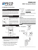
Wiring Diagram
NC-COM-NO: Output for ON-
OFF control of fan coil operation.
Dry contact signal.
24 V: Power supply (non-polarity)
4. Replace the front cover and then perform the walk
test.
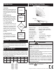
Walk Test
Apply the power supply to the sensor and wait for about 45
seconds to warm unit up. The LED will blink (long-short)
during warm up period. Ensure the jumper head connectors
of ON and OFF delays are placed on “A” position (shortest
delay). Walk across the detection zones (invisible) at normal
speed. The LED will light whenever the sensor detects the
motion. Note: If any jumper is not properly placed, the LED
will blink.
Ceiling Mount
Wall Mount
© Copyright 2004 PECO, Inc. All Rights Reserved P/N 68737 3220-1386 Rev1 Page 1
Do not install where unit is
exposed to direct sunlight or
directly above strong sourcesof
heat.
Make sure the detection area does
not have any obstruction (plants,
large pieces of furniture, curtains
etc.) which may block the
detection.
INSTALLATION HINTS
3. Connect the cable to the corresponding terminals
according to the following instructions.
DESCRIPTION
Installation Instructions
SB200-001
HVAC Occupancy Sensor