
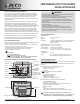
Install Instructions


© COPYRIGHT 2010 PECO, INC. ALL RIGHTS RESERVED. P/N 70480 3220-2269 REV 00
1
Thank you for choosing a PECO
Performance PRO™ thermostat. The Performance
PRO T12000 Series is intended for use in residential and commercial environments. It
is designed for and can support up to 3-HEAT/ 2-COOL con gurations in conventional
systems and in heat pump applications. The Performance PRO also provides the
capability to meet the requirements for ASHRAE 90.1-2004 and California Building Code
Title 24 (2008 edition).
The Performance PRO T12000 Series is comprised of the T12000 non-programmable
thermostat models and the T12500 programmable thermostat models. The T12000
Series features a 12 square inch blue backlit display with dynamic menus, accessed
using touchscreen keys. All Performance PRO T12000 Series offer the following standard
features: auto-changeover, temporary override, optional remote sensors, occupancy
sensors, three levels of keypad lockout, a PIN access code, a furnace lter change
reminder. The T12500 programmable models contain: up to four scheduled events per
day, a 365-day calendar, 20 holidays, holiday override, temporary override, a Power
Harvesting feature to preserve battery life (also known as “power stealing”), Secure Digital
(SD) card capability (card not included), and optional humidity control (T12532-IAQ only).
The T12000 Series can be powered by 24 VAC or batteries or both (recommended).
The T12000 Series can control up to 7 outputs and monitor three external sensors. The
T12000 Series mounts onto any PECO Performance PRO Series wallplate.
PECO Performance PRO is intended for use in conventional and heat pump applications.
• System mode selections: Off-Heat-Cool-Auto-Emergency
• Stages: 1 Heat/1 Cool, 2 Heat/1 Cool, 1 Heat/2 Cool; 2 Heat/ 2 Cool; 3 Heat/ /2 Cool
• Fan control: Cycling (Auto) or Continuous (On); 1 Speed
• Permanent memory: All device settings are stored in permanent memory.
• Connections for Remote Sensors (indoor, outdoor, and occupancy)
• SD card capability (card not included)
•
•
•
•
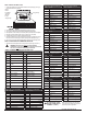
Temperature Control
Range: 50° to 90° F (10° to 32° C)
Differential: 1° F (0.5°C)
Input Power: 24 VAC (20-30 VAC) 50/60 Hz (+/- 10%) or AA alkaline batteries
(both recommended); 5mm terminals accept 14-24 AWG
stranded or solid wire.
Operating Temperature: 0° to 120°F (-17° to 48°C)
Shipping Temperature: -20° to 130°F (-28° to 54°C)
Operating Humidity: 5% to 95% RH, non-condensing
Physical Dimensions: T12000/T12500 Thermostat: 5.7” W x 4.3” H x 1.3” D
with 4” x 3” / 12 square inch liquid crystal display (LCD)
Output Ratings
Voltage (50/60 Hz): 20-30 VAC
Current: 0.02-1.0 A per terminal; W1 (B/O), W2 (AUX), G, A, E, Y1, Y2.
Note: Collectively, total current draw must not exceed 2.5 A.
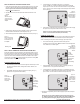
Select an appropriate thermostat location
Locate the thermostat about four feet (1.2m) above the fl oor on a wall in an area with good
ventilation and an average temperature, where it will be responsive to changes in room
temperature.
The Performance PRO T12000 Series may be mounted on a:
• Horizontal or vertical 2” X 4” device box
• Horizontal 4” X 4” device box
• Flat surface
Do locate the thermostat where it can be affected by:
• Direct sunlight
• Drafts or dead areas behind doors
• Radiant heat from appliances
• Concealed pipes or chimneys
• Outside walls or unheated/uncooled areas
Required components (not included, unless otherwise speci ed):
• Two new AA batteries (included)
• Screws and wall anchors (included)
• Screwdrivers: Phillips (for wallplate); small fl athead (for terminal blocks)
• Drill with 3/16” drill bit (or 7/32” for plaster)
• Wirecutter and stripper
• Level
• Performance PRO T12000 Series Thermostat (included)
• Performance PRO T12000 Series Thermostat Operating Manual (included)
• READ THESE INSTRUCTIONS CAREFULLY BEFORE ATTEMPTING TO INSTALL,
OPERATE OR SERVICE THIS THERMOSTAT.
• Failure to observe safety information and comply with instructions could result in
PERSONAL INJURY, DEATH AND/OR PROPERTY DAMAGE.
• To avoid electrical shock or damage to equipment, disconnect power before
installing or servicing and use only wiring with insulation rated for full thermostat
operating voltage.
• To avoid potential re and/or explosion do not use in potentially fl ammable or
explosive atmospheres.
• Retain these instructions for future reference.
• This product, when installed, will be part of an engineered system whose
speci cations and performance characteristics are not designed or controlled
by PECO. Review applications and national and local codes to assure that the
installation will be functional and safe.
▲
i
▲
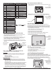
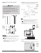
Mounting holesMounting holes
Figure 2. T12000/T12500 Thermostat
back view (with wallplate attached).
Wiring passage
Clean screen
Digital display with blue backlight
Digital display with blue backlight
Override key
Keypad Lockout,
Battery Indicator,
Service Indicator,
SD card
System key
Temperature
(indoor)
Fan (On/Auto)
Current time
Holiday key
Clock key
Current day
Recovery Mode
Cool Setpoint
(adjustable)
Heat Setpoint
(adjustable)
Schedule
Figure 1. T12000/T12500 Thermostat
(Home Display)