
Install Instructions
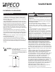

1. Install the T155 with the two furnished mounting screws to
a standard 2" x 4" electrical box, 4-11/16" x 2-1/8" square
device box with a 2" x 4" adapter ring or to a 4" x 4" box with
accessory adapter plate.
2. For wall installations, mount the thermostat on an inside
wall approximately 5 feet above the floor. The location should
provide circulation at average room temperature. Avoid direct
sunlight or sources of hot or cold air in the room or wall.
3. Remove the knob and then the cover. Mount thermostat
base assembly to the outlet box using the screws provided,
tighten the screws evenly but do not over tighten. Make wiring
connections as noted.
4. To use a remote sensor, remove jumper JP-1 to disable
local sensing. Failure to remove JP-1 when using a remote
sensor will cause improper operation of the thermostat. Some
units do not have remote sensing capability. See Application
Notes.
5. Reinstall the cover assembly. Install cover locking screw
provided. Reinstall the knob.
6. Checkout: After wiring and installation are complete,
energize the system and check the operation. Adjust the
thermostat as necessary to complete at least one cycle. Be
sure the thermostat and all other equipment are functioning
correctly.
© Copyright 2005 PECO, Inc. All Rights Reserved P/N 68745 3220-1406 Rev0 Page 1
Installation Instructions
TA155/TB155
INSTALLATION
CAUTION
•Use Copper wire only, insulate or wire
nut all un-used leads.
•Any wiring, including the remote probe,
may carry the full operating voltage of
the thermostat.
• READ THESE INSTRUCTIONS CAREFULLY BEFORE
ATTEMPTING TO INSTALL, OPERATE OR SERVICE THIS
THERMOSTAT.
• Failure to observe safety information and comply with
instructions could result in PERSONAL INJURY, DEATH AND/
OR PROPERTY DAMAGE.
• To avoid electrical shock or damage to equipment,
disconnect power before installing or servicing.
• To avoid electric shock or damage to equipment, use only
wiring with insulation rated for full thermostat operating
voltage.
• To avoid potential fire and/ or explosion do not use in
potentially flammable or explosive atmospheres.
• Retain these instructions for future reference. This product,
when installed, will be part of an engineered system whose
specifications and performance characteristics are not
designed or controlled by PECO, Inc. You must review your
application and national and local codes to assure that your
installation will be functional and safe.
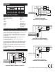
WARNING
INSTALL COVER
LOCKING SCREW
REMOVE JP1
WHEN USING A
REMOTE SENSOR
JP1
Temperature Range: 50°F - 90°F (10°C - 32°C)
TA155: A HEAT-OFF-COOL system switch manually selects
heating or cooling mode. In the HEAT position, only the heat
output cycles with demand. In the COOL position, only the cool
output cycles with demand. In the OFF position, heating and
cooling outputs are off. Units with a two position system switch
or without a system switch must use a load transfer switch when
both heating and cooling outputs are used. This prevents control
failure and equipment damage caused by direct cycling between
loads.
TB155: An ON-OFF system switch enables auto-changeover of
heating and cooling modes. In the ON position the thermostat
activates heating or cooling outputs dependant upon the
relationship between set point and ambient temperature. Heat on
to cool on dead band is 4°F. In the OFF position, heating and
cooling outputs are off. Units without a system switch cycle
between heating and cooling with a 4°F dead band.
FAN: Some units have a switch for manual selection of fan
speed. On these units fan operation is either internally wired for
fan continuous operation or is dependant upon connection to the
fan supply input . When internally wired for fan continuous
operation, the fan will be off when the system switch is off. When
dependant upon external connections the fan may not be off with
the system switch in the off position. The fan supply input is
switched to fan speed outputs (HI - MED - LO).
SWITCHED POWER: L1 power is switched to this output any
time the system switch is out of the OFF position.
THERMOSTAT OPERATION