
Install Instructions

TA/TB180 THERMOSTAT
INSTALLATION INSTRUCTIONS
READ THESE INSTRUCTIONS CAREFULLY BEFORE
ATTEMPTING TO INSTALL, OPERATE OR SERVICE THIS
THERMOSTAT.
Failure to observe safety information and comply with instructions
could result in PERSONAL INJURY, DEATH AND/OR PROPERTY
DAMAGE.
To avoid electrical shock or damage to equipment, disconnect
power before installing or servicing and use only wiring with
insulation rated for full thermostat operating voltage.
Before installing this control, the Voltage Selection Switch must be
placed in the correct position. See instructions.
To avoid potential re and/or explosion do not use in potentially
ammable or explosive atmospheres.
Retain these instructions for future reference. This product, when
installed, will be part of an engineered system whose specications
and performance characteristics are not designed or controlled by
PECO. You must review your application and national and local
codes to assure that your installation will be functional and safe.
•
•
•
•
•
•
WARNING
CAUTION
Use copper wire only, insulate or wire nut all unused leads.
Care should be used to avoid electrostatic discharge to the T180
thermostat.
This unit has conguration jumpers. You may need to recongure this
thermostat for your application.
APPLICATIONS AND FEATURES
For 2 or 4 Pipe Fan Coil and On/Off Control Applications
7 Day, 4 Event Programmability
System Selection: Off-Heat-Cool-Auto-Setback
6 Outputs: 1H, 1C, Up to 3 Fan, OA Damper
Fan Control: 1-3 Speeds
Cycling (Auto) or Continuous (On)
Automatic Fan Speed Staging (TB180 models only)
Connections for:
Fan Coil Pipe Sensor
Remote Temperature Probe
Occupancy Control
Door Switch or Setback
Condensate Overow
SPECIFICATIONS
Temperature Set Point Range 50 to 90°F / 10 to 32°C
Differential 1°
Memory – Back-Up EEPROM, No batteries required,
Stores settings for unlimited time
Mounting Installs on standard 4” x 4”
device box with a 2” x 4”
horizontal mud ring
Physical Dimensions 4.4”H x 5.8”W x 1.1”D
Agency Approvals UL, UL Canada
Electrical Ratings (see Ratings table)
•
•
•
•
•
•
•
•
•
•
•
•
▲
!
INSTALLATION
New Installations
The thermostat should be used indoors only. It should be mounted on an inner
wall in a location with freely circulating air, and where it will be responsive
to changes in room temperature. Avoid mounting near heat generating
appliances (i.e. TV, heater, refrigerator), or in direct sunlight.
Remove Old Thermostat
Turn off power to thermostat at main fuse or circuit breaker box. Ensure
that ALL power is disconnected. To prevent electrical shock and /or
equipment damage, disconnect electrical power to the system at
the main fuse or circuit breaker until installation is complete.
Remove the front cover of old thermostat. With wires still attached,
remove wall plate from the wall. If the old thermostat has a wall
mounting plate, remove the thermostat and the wall mounting plate
as an assembly.
Before removing wires from old thermostat, label each wire with
the terminal designation from which it was attached.
Disconnect the wires from the old thermostat one at a time. Do not let
wires fall back into the wall.
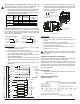
Jumper and Circuit Board Selections
Voltage Selection Switch: This switch must be placed in the appropriate
position prior to application of power.
24V = 24 VAC
110-277 V = 120, 240 or 277 VAC
JP1 Jumper Selection – Remote Temperature Sensor:
Local Sensing – Install JP1
Remote Sensing – Remove JP1 – Accessory sensors are available
in standard 60” lengths but can be extended to meet application
requirements.
JP3 Jumper Selection – HVAC Setback Systems: The JP3 jumper allows
the T180 to be congured for Setback, Occupancy Detection or Door Switch
Only Occupancy Operations. For further descriptions of these conditions
please see the Technical/Application Section.
Setback Operation - Remove JP3
Occupancy Detection - Install JP3
Door Switch Only - Install JP3
1.
2.
3.
4.
•
•
•
•
•
•
•
© COPYRIGHT 2009 PECO, INC. ALL RIGHTS RESERVED. P/N 69387 3220-2124 REV 2 PAGE 1
▲
!
▲
!
SYSTEM FAN PROGRAM
▲
!
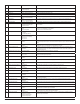
RATINGS
VOLTAGE
RES
AMPS
PILOT
DUTY
HP
24 VAC NA NA NA 24 VA NA
FLA LRA
120 VAC 5.8 34.8 6.0 125 VA 1/4
240 VAC 2.9 17.4 5.0 125 VA 1/4
277 VAC 2.4 14.4 4.2 125 VA 1/4
COMBINED LOAD CURRENT NOT TO EXCEED 20 AMPS