
Installation Manual


5 of 30
ISSUED: 07-22-08 SHEET #: 120-9054-2 09-30-11
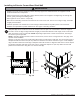
Wall plates (B) can be mounted to one or two studs that are 16" apart. Use a stud fi nder to locate the edges of
the studs. Use of an edge-to-edge stud fi nder is highly recommended. Based on their edges, draw a vertical line
down each stud’s center on both walls. NOTE: Depending on placement of studs on wall corners, mounting to
two studs may not be possible.
NOTE: If mounting speaker mounts to sides of corner mount, screen can be no larger than 40". See page 10 for
speaker mount installation.
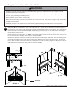
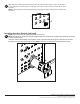
Measure 1" (25 mm) from corner of wall and mark location for inside edge of wall plate. The top mounting slots of
wall plate should be located 3.44" (87 mm) above the desired screen center as shown in fi g 1.3. Level wall plate,
align to location marked for inside edge of wall plate and mark four slots in alignment with center of studs. Repeat
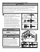
for opposite wall plate. Drill 5/32" (4 mm) dia. holes to a minimum depth of 2.5" (64 mm). Make sure that wall
plates are level and secure using #14 x 2.5" wood screws (E).
Installing to Exterior Corner Wood Stud Wall
1
• Installer must verify that the supporting surface will safely support the combined load of the equipment and all
attached hardware and components.
• Tighten wood screws so that wall plate is fi rmly attached, but do not overtighten. Overtightening can damage the
screws, greatly reducing their holding power.
• Never tighten in excess of 80 in. • lb (9 N.M.).
• Make sure that mounting screws are anchored into the center of the stud. The use of an "edge to edge" stud fi nder
is highly recommended.
• Hardware provided is for attachment of mount through standard thickness drywall or plaster into wood studs.
Installers are responsible to provide hardware for other types of mounting situations.
WARNING
STUD
CS = CENTER OF SCREEN
CS
CORNER
B
fig. 1.3
B
B
E
E
fig. 1.4
3.44"
(87 mm)
1"
(25 mm)