
Installation Manual


9 of 30
ISSUED: 07-22-08 SHEET #: 120-9054-2 09-30-11
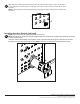
Installing Support Brackets and Center Plate
NOTE: Use center plate (D) when mounting pattern for wall plate of mount is narrower than opening
between interface plates (A).
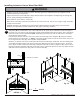
Attach support brackets (C) to rear of wall plate (B) using 1/4-20 x 1" round phillips head screw (G),
1/4" fl at washer (J) and 1/4-20 fl anged serrated locknut (H) for each support bracket as shown below.
NOTE: Be sure fl ange of support bracket faces inside of interface plate and wall plate. NOTE: Do not
fully tighten fasteners.
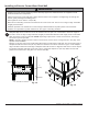
Skip to step 3-3 if not installing center plate.
3-1
Swing adapter brackets (C) away from front of
mount. Slide center plate (D) behind interface
plate (A) and center between the two interface
plates. Align top and bottom holes of interface
plate with slots of center plate. Hand thread
1/4-20 x 1" round phillips head screw (G) and
1/4" fl at washer (J) through top hole only.
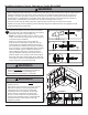
3-2
G
J
A
D
G
H
J
Swing adapter brackets (C) towards front of
mount. Guide top adapter bracket through top
screw and fasten using 1/4-20 fl anged serrated
locknut (H). Align hole of bottom adapter bracket
with bottom hole and fasten using 1/4-20 x 1"
round phillips head screw (G), 1/4" fl at washer (J)
and 1/4-20 fl anged serrated locknut (H).
3-3
G
J
H
H
J
G
C
B
A