Installation and Assembly: 2 x 2 Cart Model: DS-VWC560 MAX 1 of 12 Visit the Peerless Web Site at www.peerlessmounts.com Maximum Load Capacity 500 Ibs (227 kg) ISSUED: 03-08-11 SHEET #: 125-9195-5 09-20-12 For customer care call 1-800-865-2112.
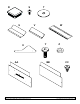
PARTS LIST A B C D E F G H I J K L M N O P Q R S T U V W X Y Z AA BB CC Description vertical support adapter brackets horizontal support horizontal rail 5" caster [127mm] 1/4" flat washer [6mm] M8 x 25 mm phillips screw 5/16 flat washer [7mm] 5/16 split washer [7mm] 1/4-20 x 3.5" hex head screw 1/4-20 nylock nut .38 OD x .
T S R U W V Y X BB AA 3 of 12 Visit the Peerless Web Site at www.peerlessmounts.com Z CC ISSUED: 03-08-11 SHEET #: 125-9195-5 09-20-12 For customer care call 1-800-865-2112.
Note: Read entire instruction sheet before you start installation and assembly. WARNING • Do not begin to install your Peerless product until you have read and understood the instructions and warnings contained in this Installation Sheet. If you have any questions regarding any of the instructions or warnings, for US customers please call Peerless customer care at 1-800-865-2112, for all international customers, please contact your local distributor.
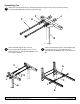
Assembling Cart 1 Attach two horizontal supports (C) to vertical support (A) using eight 1/4-20 x 3.5" hex head screws (J), 1/4" SAE washers [6mm] (F) and 1/4-20 nylock nuts (K). C K F J A 2 Attach horizontal supports (C) to second vertical support (A) using eight 1/4-20 x 3.5" hex head screws (J), 1/4" SAE washers [6mm] (F) and 1/4-20 nylock nuts (K). 3 Attach horizontal support (C) to vertical supports (A) using eight 1/4-20 x 3.
4 Attach four swivel casters [127mm] (E) to vertical supports (A) using sixteen M8 x 25 mm pan phillips screws (G), split washers (I) and 5/16" SAE flat washers [8mm] (H). G I H A 5 E Determine position of horizontal rails (D) using the formula below. 1. Locate the position of the lower horizontal rail (D) and attach to vertical supports (A). 2. Use display height to determine location of upper horizontal rail (D), NOTE: Lowest horizontal rail (D) position shown in detail 1.
6 Attach horizontal rails (D) onto vertical supports (A) using sixteen 1/4-20 x 3.5" hex head screws (J), 1/4" SAE washers [6mm] (H) and 1/4-20 nylock nuts (K) as shown in detail 1. Make sure that horizontal rails (D) are level then tighten all 1/4-20 x 3.5" hex head screws (J). Place two tube caps (R) into tops of vertical supports (A) as shown in detail 2. NOTE: horizontal rails (D) must be secured using sixteen 1/4-20 x 3.5” hex head screws (J).
Attach adapter brackets (B) to back of display using four M6 x 12 mm phillips screws (O) with nylon shoulder washer [4mm] (L), or four M8 x 15 mm phillips screws (N) as shown below. Adapter Bracket Mounting Patterns 200 mm MIN 600 mm MAX B L 200 mm 400 mm 300 mm PLP PLATE O or N Adapter Bracket Placement Detail 8.1 Use detail 3 to figure adapter bracket (B) placement. DISPLAyS NOT SHOWN FOR CLARITy 43.65" (1109 mm) MIN MIN HOLE PATTERN 68.25" (1733 mm) MAX MAX HOLE PATTERN 33.
8.2 Attach adapter brackets using the PLP Setup (B) using the M10 screws that are supplied with the PLP plate. Adapter Bracket Mounting Patterns B M10 screw supplied with PLP plate 9 of 12 Visit the Peerless Web Site at www.peerlessmounts.com ISSUED: 03-08-11 SHEET #: 125-9195-5 09-20-12 For customer care call 1-800-865-2112.
9 Hook display and adapter brackets (B) onto horizontal rail (D) as shown below. NOTE: Hang displays in sequenced order. NOTE: Once display is located in desired position, tighten security screws as shown in detail 4. 4 D 3 2 B 1 Attaching Component Shelf (Optional) 10 Fasten component shelf (W) onto horizontal support (C) using three self-tapping phillips screws (CC) as shown below. CC (Self tapping screws) W 10 of 12 Visit the Peerless Web Site at www.peerlessmounts.
Adapter Bracket Adjustment 11 Use legend below to determine position of display. NOTE: Each knob can be adjusted independently for fine tuning angle adjustments. Turn knobs CLOCKWISE to raise display height. Turn knobs CLOCKWISE to push out display. Turn knobs COUNTER-CLOCKWISE to lower display height. Turn knob COUNTER-CLOCKWISE to pull in display. UP DOWN IN OUT KNOB KNOB 11 of 12 Visit the Peerless Web Site at www.peerlessmounts.
Attaching Covers 12 NOTE: Position bottom front and back covers first Position front bottom cover (U). Secure covers in place using four decorative screws (Y) as shown below. Position back bottom cover (V). Secure covers in place using four decorative screws (Y) as shown below. Position front top cover (AA). Secure covers in place using four decorative screws (Y) as shown below. Position back top cover (BB). Secure covers in place using four decorative screws (Y) as shown below.