
Installation Manual

5 of 24
ISSUED: 08-09-10 SHEET #: 061-9059-5 07-08-15
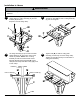
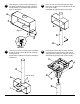
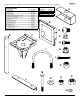
Insert two M10 x 16 mm socket screws (E) and
two split lock washers (F) into bottom of adapter
box (A) leaving 1/4" exposed thread as shown in
gure 5.1 and detail 1.
Unscrew hex nuts from u-bolts (I). Secure adapter
box (A) to support column (D) with two u-bolts (I)
and two hex nuts.
Adjust swivel of adapter box as shown and tighten
all fasteners.
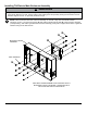
Insert one 3/8-16 x 4" at head bolt (J) through
bottom hole of support column (D) and secure with
3/8" nylock nut (K).
Set adapter box (A) onto support column (D).
Insert support column (D) into ceiling assembly
(C). Align holes of support column with holes of
ceiling assembly and secure using two 3/8-16 x 4"
at head bolts (J) and two 3/8" nylock nuts (K).
5
7
6
8
D
I
A
D
K
J
C
K
J
D
A
A
E
F
DETAIL 1
g. 5.1
1/4"
HEX NUTS (I)