
Installation Manual

7 of 24
ISSUED: 08-09-10 SHEET #: 061-9059-5 07-08-15
© 2015, Peerless Industries, Inc. All rights reserved.
All other brand and product names are trademarks or registered trademarks of their respective owners.
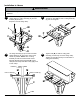
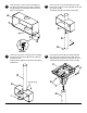
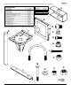
Hook tilt plate (B) onto bottom socket screws
threaded into adapter box (A) and select desired
tilt angle (0° to 20°) as shown in gure 10.1.
NOTE: Be sure split lock washer (F) is on outside
of tilt plate as shown in detail 2.
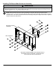
Insert two M10 x 16 mm socket screws (E) and
two split lock washers (F) through tilt plate (B) and
into top of adapter box (A) as shown in gure 10.2.
Tighten all fasteners using 6 mm allen wrench.
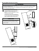
Mounting Main Enclosure Assembly
10
• Do not lift more weight than you can handle. Always use an assistant or mechanical lifting equipment to safely lift
and position the at panel screen.
• Do not tighten screws with excessive force. Overtightening can cause damage to mount. Tighten screws to
40 in. • lb (4.5 N.M.) maximum torque.
WARNING
• Do not allow main enclosure assembly to hang freely
on wall box (A) when all four sets of M10 x 16 mm
socket screws (E) are not fully secured or mount may
come off of wall.
CAUTION
g 10.1
g 10.2
B
E
MAIN ENCLOSURE
ASSEMBLY
DETAIL 2
F
A
B