User Guide ULTRAVIEW™ UHD OUTDOOR TELEVISION ENG 1 2020-01-13 #:180-9138-1
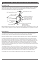
SYSTEM INSTALLATION AND ELECTRICAL REQUIREMENTS Electrical Code Note: To the display system installer: This reminder is provided to call attention to Article 820-44 of the National Electric Code that provides guidelines for proper grounding and, in particular, specifies that the cable ground shall be connected to the grounding system of the facility. Outlet shall be installed near the equipment and shall be easily accessible.
Safety Compliance FCC CAUTION To assure continued compliance and possible undesirable interference, ferrite cores may be used when connecting this display to video equipment; maintain at least 400mm (15.75 inches) spacing to other peripheral devices. FCC STATEMENT This equipment has been tested and found to comply with the limits for a Class B digital device, pursuant to Part 15 of the FCC Rule.
GENERAL SAFETY PRECAUTIONS Read before operating equipment Thank you for purchasing our product. Before using it, please read this user guide carefully and follow the instructions for safe operation. Please keep this manual for future reference and always include it when transferring or transporting this product to a different location.
• • • • • • • • • • WARNING Never apply pressure to the exterior of the LCD screen. If monitor or glass is broken, do not come in contact with the liquid crystal and handle with care. Do NOT climb on the product. Do NOT install within five feet from a body of water. Do NOT use if ambient air temperature exceeds the operating limits. Do NOT install in enclosure or recessed cavity with less than 2 inches of airflow around the display. Air inside fully encased display must be ventilated.
CONTENTS System Installation And Electrical Requirements ...................................................................................2 Electrical Code................................................................................................................................2 Power Source .................................................................................................................................2 FCC Caution......................................................................
SET UP INSTRUCTIONS Parts List Description television remote 3mm allen wrench IR extender regional power cord dust cover user guide (not shown) technical support insert (not shown) B (1) remote POWER TV DVD A (1) television D (1) IR extender MUTE SOURCE POWER CBL AUX TV VCR DVD SAT 2 3 4 5 6 7 8 9 0 1 SOURCE POWER CBL AUX TV MUTE DVD SAT VCR 2 3 4 5 6 4 5 6 7 8 9 7 8 9 LAST . 0 LAST 0 OK CH AUX SAT 1 .
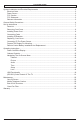
Removing Cord Cover Unscrew (2) captivated thumbscrews and remove cord cover plate to access source connection panel. Do not disconnect lanyard. A lanyard Installing Power Cord Insert female end of power cord (E) into power port located inside the input compartment.
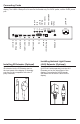
Connecting Cords Connect source devices to appropriate display input. Make all connections prior to powering on the display. The USB 2.0 Data port is for service and media only. For 5VDC power, use the 5VDC power port. AC INLET ANTENNA ANTENNA VGA Audio S/PDIF IN OPTICAL AC INLET YPbPr CVBS 5V/2.4A DC OUT CVBS YPbPr S/PDIF Optical VGA 3 USB 5VDC 2.4A HDMI 2 Audio In HDMI HDMI 3 (MHL) DisplayPort USB 2.0 Data Audio Out HDMI 1 12VDC 2.5A IR IN RS-232 IR OUT ALS IN 12V/2.
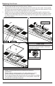
Replacing Cord Cover 1. 2. 3. 1 Run power and signal cords through notches. To prevent unwanted interference, route the power cord through the right most notch (see image 1 below). Place the cord cover over the cords being careful not to pinch any of the cords. Loosely install (6) M5 hex cap screws then tighten screws on the cord cover using 3mm allen wrench (C) until the gasket on the cover is fully compressed to the cord gasket .
Connect To The Power Source Connect power cord to GFCI outlet.
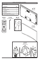
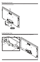
Prepare The Display For Mounting Install cords prior to mounting your display. Input panel may be obstructed once the display is mounted. A mounting solution is sold separately. Contact your Peerless-AV representative for an outdoor rated mounting solution for your particular application. For your safety, only install an outdoor-rated mount that is suitable for the application and supports the weight of the display.
Prepare The Display For Mounting Model A B C D E UV862 76.87" (1953mm) 44.24" (1124mm) 74.47" (1891mm) 41.83" (1062mm) 85.
Remote Control Battery Installation And Replacement The remote control is powered by two 1.5V AAA batteries installed at the factory. To install or replace batteries: 1. To remove the battery module of the remote control, remove the two screws on the end of the battery module. Slide the battery module out1 of1 2the12 3 remote control. 23 3 4 4 5 45 6 56 6 2. Insert two new “AAA” size batteries into the 7 7 8 78 9 89 9 . . 0 module. battery 0. 0 3.
OPERATING INSTRUCTIONS Power On/Off The Display Power on your TV by using the remote control or the rear power button on the side of the TV. The TV will power on but image may not appear for several seconds as it completes its power up sequence. Point the remote control at the IR sensor located at the top, left-hand corner of the TV and press the power button PO W ER TV M UT DV VC 1 R 4 5 .
Navigating The On Screen Menu Picture Channel Air / Cable Picture Mode Choose between antenna and cable Auto Scan Searches for available channels Color Temp. Cool Normal Warm Personal Favorite Shows favorite channels Show/Hide Show or hide channels Channel No.
Navigating The On Screen Menu Time Sleep Timer off 5 min 10 min 15 min 30 min Time Zone Atlantic Eastern Central Mountain Time Format Setup 60 min 90 min 120 min 180 min 240 min Menu Languages English Spanish French German Italian Russian Pacific Alaska Hawaii Korean Transparent (Menu Transparency) 12-hour / 24-hour 75% 100% Closed Caption CC On CC On Mute CC Off Auto Sync On / Off Clock Year (User Define) Month: 1 - 12 Day: 1 - 31 Hour: 12am - 11pm Minute: 0 - 60 Wake Up 0% 25% 50% Restore Def
Navigating The On Screen Menu Lock System Lock Enter Password to enter System Lock settings Defaut Password: 0000 Change Allows the password to be password changed System Lock On / Off Input Block TV, AV, Component, DP, HDMI 1, HDMI 2, HDMI 3, PC, USB Unrated On /Off Hotel Mode Enter password to enter hotel mode settings Defaut Password: 0000 Hotel Mode On / Off Change Allows the password to be Password changed Picture Mode Standard, Dynamic, Theater, Personal Sound Mode Standard, Music, Movie, Sports, P
USB Functionality 1 2 ENG Insert USB flash drive into USB 2.0 Data ENG Select USB source to access content. port on the input panel of the display. Input Source TV AV Component DP HDMI1 HDMI2 USB 2.
USB Functionality 3 ENG Select media type and folder where content is stored. PHOTO PHOTO Return Return 4 POWER TV MUTE DVD CBL VCR MUSIC MUSIC MOVIE MOVIE TEXT TEXT C C Photos – To view a single photo, select photo and press play. To view a slide show, select multiple photos and press play. Use on screen menu to control slide show. Movies – To view a single video, select video and press play. To view a playlist, select multiple videos and press play. Use on screen menu to control playlist.
(RS-232C) Serial Control Of The Display Attach an RS-232C cable (straight through type) to the supplied D-Sub RS-232C to utilize serial control function. Control via RS232 should only be utilized by experts familiar with RS232 programing.
MAINTENANCE Care Of The Screen Do not rub or strike the screen with anything hard as this may scratch, mark, or even damage the screen permanently. Ensure that the TV is installed in a location where it will be safe from abrasives and flying debris, which could damage the LCD panel. Never use ammonia or any product containing ammonia, as it will damage the anti-glare coating on the face of the display. Only use an approved screen cleaner to clean the display face.
Clean Fan Filter 1 2 Remove cover. UV862 3 Clean fan filter by running under water until clean. 23 Replace filter and cover.
ENG Warranty ITL Garanzia ESP Garantía ČEŠ Záruka FRN Garantie SLK Záruka DEU Garantie POR Garantia NEL Garantie TÜR Garanti̇ www.peerless-av.com/warranty Peerless-AV 2300 White Oak Circle Aurora, IL 60502 Email: tech@peerlessmounts.com Ph: (800) 865-2112 Fax: (800) 359-6500 www.peerless-av.com Peerless-AV Europe Unit 3 Watford Interchange, Colonial Way, Watford, Herts, WD24 4WP, United Kingdom Customer Care 44 (0) 1923 200 100 www.peerless-av.com Peerless-AV América Latina Av.