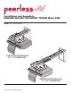
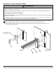
Installation and Assembly: DUKANE PROJECTOR SHORT THROW WALL ARM Model: UST-WALLARM3 PROJECTOR POSITION FOR 60" - 70" SCREEN SIZE PROJECTOR POSITION FOR 70" - 100" SCREEN SIZE 430-User Guide UST-WALLARM3-00
WARNING • Do not begin to install your Peerless product until you have read and understood the instructions and warnings contained in this Installation Sheet. If you have any questions regarding any of the instructions or warnings, for US customers please call Peerless customer care at 1-800-865-2112, for all international customers, please contact your local distributor.
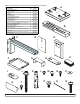
Before you start make sure all parts listed are included with your product. PARTS LIST A B C D E F G H I J K L M N O P Q R S T U Description adapter plate assembly extension bracket wall arm bracket wall plate wall plate cover projector tilt plate cable management bracket projector attachment bracket shim spacer plate #14 x 2.
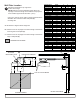
Wall Plate Location Determine and mark the top edge of the 1 screen active image. NOTE: Make sure to leave adequate space above the top edge of the active image for the wall arm and projector to be installed. Approximate dimension (23.0") Using your mark for the top edge of active image determine dimension B to locate the bottom wall plate (D) mounting hole.
Installation to Single Wood Stud Wall WARNING • Installer must verify that the supporting surface will safely support the combined load of the equipment and all attached hardware and components. • Tighten wood screws so that wall plate is firmly attached, but do not overtighten. Overtightening can damage the screws, greatly reducing their holding power. • Never tighten in excess of 80 in. • lb (9 N.M.). • Make sure that mounting screws are anchored into the center of the stud.
Installation to Solid Concrete or Cinder Block WARNING • When installing Peerless wall mounts on cinder block, verify that you have a minimum of 1-3/8" (35 mm) of actual concrete thickness in the hole to be used for the concrete anchors. Do not drill into mortar joints! Be sure to mount in a solid part of the block, generally 1" (25 mm) minimum from the side of the block. Cinder block must meet ASTM C-90 specifications.
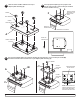
2 Remove knobs and M10 washers from top of adapter plate assembly (A). 3 Place projector tilt plate (F) onto projector and secure using four M4 x 8 mm socket pin serrated washer head screws (L).
5 Fasten two M5 x 20 mm socket pin serrated washer head screws (R) into top of adapter plate assembly (A) leaving 3/8" of exposed thread as shown below. 6 Fasten one M5 x 20 mm socket pin serrated washer head screws (R) into top of projector attachment bracket (H) leaving no exposed thread on bottom of bracket as shown below. R R 3/8" H R A H FLUSH WITH BOTTOM 7 Slide two cable management brackets (G) into channel in wall arm bracket (C) as shown below.
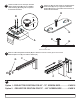
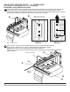
PROJECTOR POSITION FOR 60" - 70" SCREEN SIZE SKIP TO PAGE 9 IF MOUNTING WITH 70" - 100" SCREEN SIZE Installation using Wall Arm Bracket exposed M5 x 20 mm socket pin serrated washer head screws (R) on top of adapter plate assembly (A) 9 Attach through slot in wall arm bracket (C) and keyholes in projector attachment bracket (H) as shown in detail 1. Slide projector attachment bracket (H) toward wall.
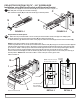
PROJECTOR POSITION FOR 70" - 100" SCREEN SIZE Installation using Wall Arm Bracket and Extension Bracket 9 Snap extension cap (U) into extension bracket (B) in orientation as shown in figure 9.1. Slide wall plate cover (E) onto wall arm bracket (C). Slide extension bracket (B) into wall arm bracket (C) in desired position. C B B U FIGURE 9.1 10 FIGURE 9.2 E Requirements for Shim Spacer 1.
Installation using Wall Arm Bracket and Extension Bracket Attach exposed M5 x 20 mm socket pin serrated washer head screws (R) into top of adapter plate assembly (A) 11 through slot in extension bracket (B) and keyholes in projector attachment bracket (H) as shown in detail 5. Slide projector attachment bracket (H) toward wall. Once in locked position tighten all three M5 x 20 mm socket pin serrated washer head screws (R) using security wrench (Q) as shown in detail 6.
Roll Adjustment 14 Loosen knobs on left side of projector, and tighten knobs on right side of projector to roll projector to the right. Reverse for projector roll to the left. LOOSEN TIGHTEN DO NOT ADJUST SUPPORTING SURFACE NOT SHOWN FOR CLARITY Pitch Adjustment Loosen knobs on front of projector, and tighten knobs on back of projector to pitch projector forward. Reverse for projector to pitch backward.
Combination for Pitch and Roll Rotation Loosen knob on back right of projector, and tighten knob on left front of projector to pitch and rotate projector backward to the right as shown in fig. 13.2. Reverse for projector to pitch backward to the left. Tighten knob on back right of projector, and loosen knob on left front of projector to pitch and rotate projector backward to the right as shown in fig. 13.1. Reverse for projector to pitch backward to the left. SUPPORTING SURFACE NOT SHOWN FOR CLARITY Fig.
Secure wall plate cover (E) to wall arm bracket (C) using two M5 x 10 mm socket pin serrated washer head screws (T). Note: Adjust height of wall plate prior to fastening wall plate cover (E) for projector image location. Use security wrench (Q) to fasten screws. T C E SUPPORTING SURFACE NOT SHOWN FOR CLARITY 14 of 14 ISSUED:07-25-11 SHEET #: 125-9225-1 © 2009 Peerless Industries, Inc. All rights reserved. Peerless is a registered trademark of Peerless Industries, Inc.