Series MI/MIH™ Gas Boilers Installation, Operation & Maintenance Manual
TABLE OF CONTENTS TABLE OF CONTENTS USING THIS MANUAL 1 A. INSTALLATION SEQUENCE . . . . . . . . . . . . .1 B. SPECIAL ATTENTION BOXES . . . . . . . . . . . .1 1. PREINSTALLATION 2 A. ACCESSIBILITY CLEARANCES . . . . . . . . . . .2 B. CLEARANCE FROM COMBUSTIBLE CONSTRUCTION . . . . . . . . . . . . . . . . . . . . . .2 C. AIR FOR COMBUSTION AND VENTILATION . . . . . . . . . . . . . . . . . . . . . . . . .2 D. INSTALLATION SURVEY . . . . . . . . . . . . . . . .5 E. PLANNING THE LAYOUT . . . . . . . . . . .
USING THIS MANUAL USING THIS MANUAL A. INSTALLATION SEQUENCE Follow the installation instructions provided in this manual in the order shown. The order of these instructions has been set in order to provide the installer with a logical sequence of steps that will minimize potential interferences and maximize safety during boiler installation. B.
PREINSTALLATION 1. PREINSTALLATION Read carefully, study these instructions before beginning work. This boiler must be installed by a qualified contractor. The boiler warranty can be voided if the boiler is not installed, maintained and serviced correctly. NOTICE The equipment must be installed in accordance with those installation requirements of the authority having jurisdiction or, in the absence of such requirements, to the current edition of the National Fuel Gas Code, ANSI Z223.
PREINSTALLATION where: Iother = Input of appliances other than fan assisted in Btu/hr ACH = air change per hour (percent of the volume of the space exchanged per hour, expressed as a decimal) For fan assisted appliances, calculate the required volume of air using the following equation: Ifan 15 ft3 ⎛ I fan ⎜ ACH ⎝ 1000Btu/hr ⎛ ⎜ ⎝ Required Volumefan = = Input of the fan assisted appliances in Btu/hr Note: These calculations are not to be used for infiltration rates greater than 0.60 ACH. 3.
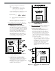
PREINSTALLATION Figure 1.4: Air Openings – All Air from Outdoors through Vertical Ducts ii. Where communicating with the outdoors through horizontal ducts, each opening shall have a minimum free area of 1 in2 per 2000 Btu/hr (22 cm2 per 2000 W) of total rated input for all appliances in the space. See Figure 1.5. Figure 1.6: Air Openings – All Air from Outdoors through One Opening 5.
PREINSTALLATION c. Each of the appliances served shall be interlocked to the mechanical air supply to prevent main burner operation when the mechanical air supply system is not in operation. d. In buildings where the combustion air is provided by the mechanical ventilation system, the system shall provide the specified combustion air rate in addition to the required ventilation air. 8. Louvers & Grills: a.
BOILER SET-UP 2. BOILER SET-UP 1. Provide a sound, level foundation. Locate boiler as near to the chimney or outside wall as possible and centralized with respect to the heating system. 4. Separate the wood shipping pallet from the boiler base by removing two (2) hold-down bolts at each end of the boiler base. 2. Locate boiler in front of installation position before removing crate. 5. Move boiler into final position.
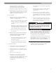
WATER PIPING AND CONTROLS 3. WATER PIPING AND CONTROLS A. BOILER SUPPLY AND RETURN 1. Size the supply and return to suit the system. A typical piping arrangement is shown in Figure 3.1. Refer also to the I=B=R Guide - Residential Hydronic Heating Installation/Design and the PB Heat Water Survey for additional guidance during water piping installation. 2. Return Piping: Pipe the drain valve to a tee, provided, and the 1-1/4 NPT return tapping near the bottom of the left section. Pipe the return to the tee.
WATER PIPING AND CONTROLS 6. Install this boiler so that the gas ignition system components are protected from water (dripping, spraying, etc.) during appliance operation and service (circulator replacement, condensate trap, control replacements, etc.). 7. If this boiler and distribution system is used in conjunction with a refrigeration system, pipe the chilled medium in parallel with the boiler and install the proper valve to prevent the chilled medium from entering the boiler.
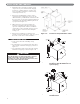
WATER PIPING AND CONTROLS C. PIPING FOR ZONED SYSTEMS 1. See Figures 3.5 and 3.6 for basic zoned system layouts. 2. Run each zone pipe down then up to zone to prevent air accumulation in piping. 3. If required, provide means to isolate and drain each zone separately. Figure 3.5: Zone Piping with Zone Valves Figure 3.
WATER PIPING AND CONTROLS D. EXPANSION TANK 1. Consult the tank manufacturer’s instructions for specific information relating to tank installation. Size the expansion tank for the required system volume and capacity. See Table 10.2 in Section 10 for boiler water content. 2. Expansion tanks are available with built-in fill valves and check valves for reducing supply water pressure and maintaining minimum system pressure. Check the design features of the tank and provide valves as necessary.
VENTING 4. VENTING A. INTEGRAL DRAFT HOOD 1. The MI/MIH™ boiler is equipped with a built-in draft hood. This device is designed to: a. provide for the ready escape of flue gases from the boiler in the event of no draft. b. prevent a backdraft from entering the boiler. B. VENT DAMPER INSTALLATION – GENERAL 1. Do not use one vent damper to control two or more heating appliances. See Figure 4.1. 2. Follow these and the installation instructions that are included with the vent damper.
VENTING C. VENT PIPING AND CHIMNEY 1. Install vent piping in accordance with Venting of Equipment part of the National Fuel Gas Code, ANSI Z223.1/NFPA 54, sections 7.2, 7.3 or 7.4 of CAN/CSA B149.1, Natural Gas and Propane Installation Code, or applicable provisions of the local building codes. 2. Inspect the existing chimney and lining for structural soundness, corrosion and perforations. Repair as necessary. 3.
VENTING D. BOILER REMOVAL FROM COMMON VENTING SYSTEM At the time of removal of an existing boiler, follow these steps with each appliance remaining connected to the common venting system placed in operation, while the other appliances remaining connected to the common venting system are not in operation: a. Seal any unused openings in the common venting system. b.
GAS PIPING 5. GAS PIPING 1. Size and install the gas supply piping properly in order to provide a supply of gas sufficient to meet the maximum demand without undue loss of pressure between the meter and the boiler. 2. Determine the volume of gas to be provided to the boiler in cubic feet per hour. To obtain this value, divide the Btu per hour rating (on the boiler rating plate) by the heating value of the gas in Btu per cubic feet. Obtain the heating value of the gas from the gas supplier.
GAS PIPING MI™ Boiler – Natural Gas Table 5.1: Input Model Cubic Feet / Hour Cubic Meters / Hour MI-03 70 2.0 MI-04 105 3.0 MI-05 140 4.0 MI-06 175 5.0 MI-07 195 5.5 MI-08 227.5 6.4 MI-09 260 7.4 MI™ Boiler – LP Gas Table 5.2: Input Model Cubic Feet / Hour Cubic Meters / Hour MI-03 28 0.8 MI-04 42 1.2 MI-05 56 1.6 MI-06 70 2.0 MI-07 78 2.2 MI-08 91 2.6 MI-09 104 2.9 MIH™ Boiler – Natural Gas Table 5.
ELECTRICAL 6. ELECTRICAL Install all electrical wiring in accordance with the National Electrical Code and local requirements. NOTICE This unit when installed must be electrically grounded in accordance with the requirements of the authority having jurisdiction or, in the absence of such requirements, with the current edition of the National Electrical Code, ANSI/NFPA 70 and/or the Canadian Electrical Code, Part 1 CSA C22.1, Electrical Code. A. WIRING C. CONTROLS 1. See Figure 6.
ELECTRICAL Figure 6.2: Wiring and Connection Diagram – Standing Pilot (Continuous Ignition) D. SEQUENCE OF OPERATION 1. Standing Pilot (See Figure 6.2 above) a. The vent damper is continuously powered. On a call for heat, limit relay R is energized, which energizes: ● ● the circulator (when used) through contact R1, and the vent damper operator through contact R2, provided that the high-limit switch is closed. The vent damper operator opens the damper. b.
ELECTRICAL Figure 6.3: Wiring and Connection Diagram – Intermittent Ignition 2. Intermittent Ignition (see Figure 6.3 above) a. The vent damper is continuously powered. On a call for heat, limit relay R is energized, which energizes: ● the circulator (when used) through contact R1, and ● the vent damper operator through contact R2, provided that the high-limit aquastat switch is closed. The damper operator opens the vent damper. b.
ELECTRICAL Figure 6.
Figure 6.5: Zone Wiring with Zone Valves Figure 6.
START-UP PROCEDURES 7. START-UP PROCEDURES A. COMPLETING THE INSTALLATION 1. Confirm that all water, gas and electricity are turned off. 2. Inspect the boiler combustion chamber for foreign objects and remove if present. 3. Check physical condition of burners and pilot. Make certain that there are no unusual bends or perforations in the burners or pilot. Replace components if necessary. 8. Connect a manometer to the gas valve on the valve outlet (gas manifold). Use the 1/8 NPT tapping provided. 9.
START-UP PROCEDURES Figure 7.1: Gas Valve, Manifold and Burner Assembly – Standing Pilot (Continuous Ignition) Figure 7.2: Gas Valve, Manifold and Burner Assembly – Intermittent Ignition Figure 7.
START-UP PROCEDURES Figure 7.
START-UP PROCEDURES FOR YOUR SAFETY READ BEFORE LIGHTING WARNING: If you do not follow these instructions exactly, a fire or explosion may result causing property damage, personal injury, or loss of life. A. This appliance has a pilot which must be lighted by hand. When lighting the pilot, follow these instructions exactly. If you cannot reach your gas supplier, call the fire department. C. Use only your hand to push in or turn the gas control knob. Never use tools.
START-UP PROCEDURES B. CONTROL DESCRIPTIONS See Figure 6.1 in Section 6 (Electrical) for locations of these devices. 1. FLAME ROLL-OUT SAFETY SHUT-OFF SWITCH (FLAME ROLL-OUT SWITCH) – A thermally activated switch located between the first burner from the left and the manifold bracket. The flame roll-out safety shut-off switch will sense excessive temperature caused by continued flame roll-out and shut down main burner gas.
START-UP PROCEDURES Table 7.1b: E. CHECKING BURNER INPUT 1. Refer to rating label mounted on the jacket top panel to obtain the rated BTU per hour input. In no case shall the input to the boiler exceed the value shown on the rating label. 2. Check input by use of the following formulas (PB Heat, LLC suggests reading meter for 2 Cu. Ft.): Burner inputs in kW for for various meter timings and heat values. (Table based on 0.0566 cubic meter of gas through meter). U.S. Customary Units Input (BTU/Hr.
START-UP PROCEDURES b. Intermittent Ignition System: i) Turn gas supply off. ii) Set thermostat or controller above room temperature to call for heat. Watch for igniter glow at pilot burner. iii) Igniter will continue to glow for 30 seconds, de-energize for 30 seconds, then re-energize and glow for another 30 seconds. It will then de-energize for 5 minutes before restarting the sequence. iv) Turn gas supply on. v) Reset the boiler and control by following Operating Instructions.
TROUBLESHOOTING 8. TROUBLESHOOTING A. SHUT-DOWN CAUSED BY PILOT OUTAGE, BLOCKED VENT SHUT-OFF SWITCH OR FLAME ROLL-OUT SAFETY SHUT-OFF SWITCH In the event of a shut-down caused by a pilot outage, action of the blocked vent shut-off switch or flame rollout safety shut-off switch effecting a shut-down of the main burners: a. Refer to the Lighting/Operating Instructions in Figures 7.4 and 7.5 to properly turn off the gas to the boiler. b. Turn off all electric power to the boiler. c.
TROUBLESHOOTING Table 8.1: Boiler Troubleshooting Guide PROBLEM Burners not functioning. POSSIBLE CAUSES 1. No power. 2. Limit (Aquastat) not working. 3. Flame rollout switch open. 4. Blocked vent switch open. 5. Gas off at boiler gas valve. 6. Gas off external to boiler. 7. Plugged orifice spuds. 8. Defective gas valve. 9. Improper wiring. 10. Vent damper malfunctioning. Burners will not shut down. Flashback or burning at orifice spuds. 1. Defective gas valve. CORRECTIVE ACTIONS 1.
TROUBLESHOOTING Figure 8.
MAINTENANCE 9. MAINTENANCE WARNING Product Safety Information Refractory Ceramic Fiber Product This appliance contains materials made from refractory ceramic fibers (RCF). Airborne RCF, when inhaled, have been classified by the International Agency for Research on Cancer (IARC), as a possible carcinogen to humans. After the RCF materials have been exposed to temperatures above 1800°F (980°C), they can change into crystalline silica, which has been classified by the IARC as carcinogenic to humans.
A. GENERAL 1. Disconnect this boiler from the gas supply piping during any pressure testing of the gas system. 2. Check pipes adjacent to cold walls or in unheated spaces. Insulate and tape them if necessary to be sure they can’t freeze up. Keeping the water moving at all times will reduce the likelihood of freezing. See Section 3 for glycol instructions. 3.
MAINTENANCE E. ANNUALLY (BEFORE START OF HEATING SEASON) DANGER When servicing or replacing components, be absolutely certain that the following conditions are met: Water, gas and electricity are off. The boiler is at room temperature. There is no pressure in the boiler. ● ● ● 1. Check flueways and burners for cleanliness and clean if necessary. Use the following procedure if cleaning is required: a. Refer to the Lighting/Operating Instructions in Figures 7.4 and 7.
BOILER DIMENSIONS & RATINGS 10. BOILER DIMENSIONS & RATINGS Figure 10.1:Boiler Views Table 10.
BOILER DIMENSIONS & RATINGS 11. REPAIR PARTS REPAIR PARTS SERIES MI/MIH™ GAS BOILER Repair parts are available from your installer or by contacting PB Heat, LLC, 131 S. Church St., Bally, PA 19503. Use the figures and tables on pages 35-41 to assist in ordering parts. Note: Remember to include boiler model number and serial number when ordering parts. Figure 11.1: Base/Combustible Floor Pan Table 11.
REPAIR PARTS Figure 11.2: Manifold Figure 11.3a: Gas Valve and Pilot – Standing Pilot (Continuous Ignition) Figure 11.
REPAIR PARTS Table 11.
REPAIR PARTS Figure 11.4: Block/Draft Hood Figure 11.
REPAIR PARTS Table 11.
REPAIR PARTS Figure 11.
REPAIR PARTS Table 11.
Series MI/MIH™ Gas Boilers Installation, Operation & Maintenance Manual TO T H E I N S TA L L E R : This manual is the property of the owner and must be affixed near the boiler for future reference. TO T H E O W N E R : This boiler should be inspected annually by a Qualified Service Agency. ASME PB HEAT, LLC 131 S. CHURCH STREET • BALLY, PA 19503 ©2011 PB Heat, LLC. All rights reserved. MI8038 R13 (6/11-3M) Printed in U.S.A.