Series 63/64™ Gas Boilers Installation, Operation & Maintenance Manual
TABLE OF CONTENTS TABLE OF CONTENTS USING THIS MANUAL 1 A. MANUAL ORGANIZATION . . . . . . . . . . . . . .1 B. SPECIAL ATTENTION BOXES . . . . . . . . . . . .1 5. FUEL PIPING 16 A. INSTALLATION . . . . . . . . . . . . . . . . . . . . . . .16 B. OPERATION . . . . . . . . . . . . . . . . . . . . . . . . .16 1. PREINSTALLATION 2 A. GENERAL . . . . . . . . . . . . . . . . . . . . . . . . . . . .2 B. CODES & REGULATIONS . . . . . . . . . . . . . . . .2 C. ACCESSIBILITY CLEARANCES . . . . . . . . . . .2 D.
USING THIS MANUAL USING THIS MANUAL A. INSTRUCTION MANUALS The Series 63/64™ Installation, Operation & Maintenance Manual is divided into four basic sections: 1. 2. 3. 4. Preinstallation (Section 1) Installation (Sections 2 through 8) Start-Up (Section 9) Maintenance (Section 10) B. SPECIAL ATTENTION BOXES Throughout this manual special attention boxes are provided to supplement the instructions and make special notice of potential hazards.
PREINSTALLATION 1. PREINSTALLATION A. GENERAL Series 63/64™ boilers are supplied knocked down for field assembly or completely assembled as packaged boilers. All items should be inspected for damage upon receipt and any damage reported to the trucker and wholesaler. All components should be stored in a clean dry area. Carefully read these instructions before beginning work. Understand all aspects of the installation. Contact PB Heat sales representative or customer service for help in answering questions.
E. AIR FOR COMBUSTION AND VENTILATION 1. Adequate combustion air and ventilation air must be provided for this appliance in accordance with the section of the National Fuel Gas Code entitled, “Air for Combustion and Ventilation” or applicable provisions of the local building code. Subsections 2 through 8 as follows are based on the National Fuel Gas Code requirements. 2.
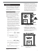
PREINSTALLATION 4. Outdoor Combustion Air: Outdoor combustion air is to be provided through one or two permanent openings. The minimum dimension of these air openings is 3 inches (76 mm). a. Two Permanent Opening Method: Provide two permanent openings. One opening is to begin within 12 inches (305 mm) of the top of the space and the other is to begin within 12 inches (305 mm) of the floor.
5. Combination Indoor and Outdoor Combustion Air: If the required volume of indoor air exceeds the available indoor air volume, outdoor air openings or ducts may be used to supplement the available indoor air provided: a. The size and location of the indoor openings comply with Subsection 3. b. The outdoor openings are to be located in accordance with Subsection 4. c.
PREINSTALLATION WARNING Liquefied Petroleum (LP) is heavier than air and may collect or “pool” in a low area in the event of a leak from defective equipment. This gas may then ignite, resulting in a fire or explosion. F. INSTALLATION SURVEY For new and existing installations, a Water Installation Survey or a Steam Installation Survey is available from PB Heat, LLC.
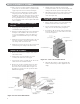
BOILER PLACEMENT & ASSEMBLY 2. BOILER PLACEMENT & ASSEMBLY A. PACKAGED BOILER 1. Remove the crate top and sides and remove any loose cartons. 2. Lift the boiler from the crate pallet. Move the boiler to the location determined in Chapter 1: Pre-installation. NOTICE Be careful not to damage the burner tray when removing the boiler from the pallet. If necessary, remove the burner tray before moving the boiler. 3. Proceed to Chapter 3: Piping the Boiler. B.
BOILER PLACEMENT & ASSEMBLY 11. If the sections do not draw together using the torque specified above, the block must be separated and the nipples replaced before reassembly is attempted. 5. Slide the burner tray under the cast iron block assembly and attach to the end sections using the 1/4" carriage bolts and nuts provided. (See Figure 2.2). 12. The sections may alternatively be drawn together using long 5/8" rods along with cast iron washers through the nipple ports.
BOILER PLACEMENT & ASSEMBLY F. KNOCKDOWN BOILER: HYDROSTATIC TESTING 4. Back Panel Jacket: Position the back jacket panel inside the flange of the side jacket panels and attach it with six #10 x 1/2" sheet metal screws. See Figure 2.5. 1. Install the pressure gauge and drain valve in the right hand end section. 2. Install a water supply line with a shut-off valve in the right hand end section. 3. Install an air vent valve on the boiler relief valve connection. 4. Plug all open tappings in the boiler. 5.
BOILER PLACEMENT & ASSEMBLY 7. Attach the Draft Hood to the Flue Collector using #10 x 1/2" sheet metal screws provided. Refer to Figure 2.7. Figure 2.7: Draft Hood Attachment 8. Position the Top Jacket Panel so that the flanges overlap the Side Jacket Panels and the air louvers are at the front of the boiler. Attach with six #10 x 1/2" sheet metal screws. See Figure 2.6. 9.
3. VENTING A. CHIMNEY OR VENT 1. Inspect the existing chimney or vent system. Make sure it is in good condition. Inspect chimney liner and repair or replace if necessary. 2. The vent system and installation must be in accordance with Venting of Equipment chapter of the current edition of the National Fuel Gas Code, ANSI Z223.1/NFPA 54, or applicable provisions of the local building codes. 3.
VENTING a. Orient the vent damper operator to facilitate connection of the vent damper harness to knockout on right side of boiler. b. Orient vent damper direction arrow in direction of vent gas flow. Direction arrow must be visible from front of boiler. CAUTION Damper must be in open position when appliance main burner is operating. a. Seal any unused openings in the common venting system. b.
BOILER PIPING 4. BOILER PIPING A. WATER BOILER PIPING – SINGLE BOILER 1. Refer to the PB Heat Water Installation Survey and Hydronics Institute Residential Hydronic Heating Installation Design Guide. 2. Figure 4.1 shows typical supply and return piping for a boiler system. If the system expansion tank is located on the boiler loop, it should be located on the supply side of the boiler with the system circulator pumping away from the expansion tank connection. 3.
BOILER PIPING B. WATER BOILER PIPING – MULTIPLE BOILERS Refer to the PB Heat Water Installation Survey and Hydronics Institute Residential Hydronic Heating Installation Design Guide for guidance on multiple boiler installations. 3. Pipe the steam header a minimum of 24" above the normal water line using swing joints to attach the risers into the steam header. Use Threaded Fittings for Manifold Piping C. STEAM BOILER PIPING – SINGLE BOILERS 1.
BOILER PIPING 6. The use of a Hartford Loop in all installations is recommended to ensure reliability of the system. A check is required on the pump discharge of all pumped return systems. 7. On pumped return systems, install a globe valve after the pump to allow throttling of the pump discharge. The pressure downstream of the boiler cock should be no more than 5 psig above the boiler operating pressure.
FUEL PIPING 5. FUEL PIPING Table 5.1: Gas Input & Valve Inlet A. INSTALLATION 1. Pipe gas to the boiler in accordance with local codes. In the absence of local regulations refer to the National Fuel Gas Code, ANSI Z223.1/NFPA 54. 2. Size and install the gas supply piping to provide a supply of gas sufficient to meet the maximum demand of all appliances without excessive pressure drop. 3.
FUEL PIPING 5. Refer to table 5.4 for minimum supply pressure for the purpose of input adjustment. Table 5.4: Minimum Supply Pressure Natural Gas Model Supply Pressure (in. Water) 63-03L 63-03 63-04L 63-04 63-05L 63-05 63-06 64-07 64-08 64-09 64-10 64-11 64-12 5.00 5.00 5.00 5.35 5.00 5.00 5.56 5.00 5.27 5.00 5.00 5.00 5.10 6. Install the boiler such that the gas ignition system components are protected from water (dripping, spraying, rain, etc.
CONTROLS & TRIM 6. CONTROLS & TRIM A. WATER BOILER CONTROLS & TRIM 1. Safety Relief Valve: a. Pipe the boiler relief valve into the 3/4" tapping on the left side of the boiler as shown in Figure 6.1. Be sure that the relief valve is sized in accordance with local code requirements. In addition, be sure that the relief valve is designed constructed and stamped in accordance with ASME Boiler and Pressure Vessel Code, Section IV. 3.
CONTROLS & TRIM B. STEAM BOILER CONTROLS & TRIM 1. Safety Valve: a. Pipe the boiler safety valve provided into the 3/4" tapping on the left side of the boiler as shown in Figure 6.4. Be sure that the relief valve is sized in accordance with local code requirements. In addition, be sure that the safety valve is designed constructed and stamped in accordance with the ASME Boiler and Pressure Vessel Code, Section IV. Figure 6.6: Gauge Glass & Low Water Cut-Off Installation 4. Gauge Glass: a.
ELECTRICAL 7. ELECTRICAL A. CONNECT SUPPLY WIRING 2. Mount the blocked vent switch in the rear of the boiler on the draft hood as shown in Figure 7.2. 1. All electrical wiring must be done in accordance with local codes. In the absence of local codes use ANSI/NFPA 70 “The National Electrical Code.” CAUTION Label all wires prior to disconnection when servicing controls. Wiring errors can cause improper and dangerous operation. Verify proper operation after servicing. 2.
ELECTRICAL 4. Mount the ignition module, if required (spark ignited units only), as shown in Figure 7.4. D. WIRING DIAGRAM INDEX Standing Pilot, Natural Gas Standing Pilot, LP Gas Spark Ignition, Natural Gas Spark Ignition, LP Gas 5. Mount the thermopilot valve (Johnson L62), if required (standing pilot only on 64-07 & 64-08 Natural Gas), as shown in Figure 7.5. Fig. 7.7 64-12 64-11 64-10 64-09 64-08 64-07 63-06 63-05L 63-04 Fig. 7.6 N/A Fig. 7.6 N/A Fig 7.8 Fig. 7.
Figure 7.6: Water Boiler with Standing Pilot. Wiring Diagram for Series 63™ and for Models 64-07 and 64-08 with LP Gas Fuel.
Figure 7.7: Water Boiler with Standing Pilot. Wiring Diagram for 64-07 and 64-08 with Natural Gas Fuel.
Figure 7.8: Water Boiler with Spark Ignition. Wiring Diagram for all Models.
Figure 7.
Figure 7.10: Steam Boilers with Float Low Water Cut-off only and Standing Pilot. Wiring Diagram for Models 64-07 and 64-08 Natural Gas Only.
Figure 7.11: Steam Boiler with Spark Ignition. Wiring Diagram for Models with Float Low Water Cut-off.
Figure 7.12: Steam Boilers with Probe Low Water Cut-off and Standing Pilot Wiring Diagram for Series 63™ and Models 64-07 and 64-08 LP Gas Only.
Figure 7.13: Steam Boilers with Probe Low Water Cut-off and Standing Pilot. Wiring Diagram for Models 64-07 and 64-08 Natural Gas.
Figure 7.14: Steam Boiler with Spark Ignition. Wiring Diagram for Models with Probe Low Water Cut-off.
Figure 7.
BOILER OPERATION 8. BOILER OPERATION 2. The pressure reducing valve on the fill line will typically allow the system to be filled and pressurized to 12 psi. Consult the valve and expansion tank manufacturer for more detailed information. 3. Check all joints and fittings throughout the system for leaks. If leaks are found, drain the system and repair as required. 4. If the water hardness is high, use water treatment to reduce the deposition of minerals in the boiler. 5.
BOILER OPERATION c. Note: If the meter is not automatically corrected for temperature and pressure, the meter reading must be corrected to actual conditions during the rate test. 6. Spark-Ignited Pilot Ignition Check a. Turn up the Operating Temperature Control for a call for heat. b. The spark-ignited pilot should ignite. 7. Check the burner and pilot flames (see Figure 8.1). The flame inner cone should be about 1-1/2" high and should have a very sharp blue color.
BOILER OPERATION WARNING Cleaning the boiler requires the use of very hot water and corrosive chemicals. Use care when handling to prevent injury. 3. Thread a 1-1/4" NPT Pipe Nipple into the “Skim Tapping” (Connection “J” in Figure 11.1). Tighten firmly. 4. Thread a 1-1/4" NPT ball valve onto the nipple and connect a 1-1/4" drain line. 5. Close all valves to the system. Provide a means of supplying fresh water to the boiler. CAUTION Do not leave the boiler unattended while performing boil out.
BOILER OPERATION FOR YOUR SAFETY READ BEFORE LIGHTING WARNING: If you do not follow these instructions exactly, a fire or explosion may result causing property damage, personal injury, or loss of life. A. This appliance has a pilot which must be lighted by hand. When lighting the pilot, follow these instructions exactly. B. BEFORE LIGHTING smell all around the appliance area for gas. Be sure to smell next to the floor because some gas is heavier than air and will settle on the floor.
BOILER OPERATION FOR YOUR SAFETY READ BEFORE LIGHTING WARNING: If you do not follow these instructions exactly, a fire or explosion may result causing property damage, personal injury, or loss of life. A. This appliance has a pilot which must be lighted by hand. When lighting the pilot, follow these instructions exactly. B. BEFORE LIGHTING smell all around the appliance area for gas. Be sure to smell next to the floor because some gas is heavier than air and will settle on the floor.
BOILER OPERATION FOR YOUR SAFETY READ BEFORE LIGHTING WARNING: If you do not follow these instructions exactly, a fire or explosion may result causing property damage, personal injury, or loss of life. A. This appliance is equipped with an ignition device which automatically lights the pilot. Do not try to light the pilot by hand. Immediately call your gas supplier from a neighbor's phone. Follow the gas supplier's instructions. B. BEFORE OPERATING smell all around the appliance area for gas.
BOILER OPERATION FOR YOUR SAFETY READ BEFORE LIGHTING WARNING: If you do not follow these instructions exactly, a fire or explosion may result causing property damage, personal injury, or loss of life. A. This appliance is equipped with an ignition device which automatically lights the pilot. Do not try to light the pilot by hand. Immediately call your gas supplier from a neighbor's phone. Follow the gas supplier's instructions. B. BEFORE OPERATING smell all around the appliance area for gas.
MAINTENANCE 9. MAINTENANCE WARNING Product Safety Information Refractory Ceramic Fiber Product This appliance contains materials made from refractory ceramic fibers (RCF). Airborne RCF fibers, when inhaled, have been classified by the International Agency for Research on Cancer (IARC), as a possible carcinogen to humans. After the RCF materials have been exposed to temperatures above 1800°F, they can change into crystalline silica, which has been classified by the IARC as carcinogenic to humans.
MAINTENANCE A. GENERAL 1. Disconnect this boiler from the gas supply piping during any pressure testing of the gas system. 2. Check pipes adjacent to cold walls or in unheated spaces. Insulate and tape them if necessary to be sure they can’t freeze up. Keeping the water moving at all times will reduce the likelihood of freezing. 3. If there is considerable foreign matter in the boiler water, the boiler should be shut down and allowed to cool, then drained and thoroughly flushed out.
MAINTENANCE 2. Inspect entire venting system for corrosion, support and joint integrity. Repair as necessary. d. Remove the vent pipe, vent damper, top jacket panels and flue collector. e. Brush flueways with wire brush. 3. Check the pilot and main burner flame. See Figure 8.1. The pilot should provide a steady flame enveloping 3/8" to 1/2" of the flame sensor. If required, adjust the pilot as stated in the gas valve manufacturer’s instructions.
TROUBLE SHOOTING – SERVICE TIPS 10.
TROUBLE SHOOTING – SERVICE TIPS Problem Burner(s) Burning with Yellow Flame Gas Spillage from Draft Hood Relief Opening Main Gas Valve Opens But No Gas Flows System or Boiler Overfilling or Excessive Make-up Water (Water Boilers) Rapid Cycling (Water Boilers) Water Hammer On Start-Up (Steam Boilers) Possible Cause Suggested Remedy Air Adjustment Screws Turned in Too Far Adjust Screws Out Low Gas Pressure in Manifold (Insufficient Air Injection) Adjust Main Gas Pressure Regulator or Check Line Pr
TROUBLE SHOOTING – SERVICE TIPS Problem Water Hammer During Mid-Cycle (Steam Boilers) Water Hammer on Shut-Down (Steam Boilers) Hammering in the Boiler (Steam Boilers) No Heat or Poor Heat Distribution in the Building (Steam Boilers) System or Boiler Overfilling or Flooding (Steam Boilers) Excessive Water Level Bounce (Steam Boilers) Rapid Cycling (Steam Boilers) 44 Possible Cause Suggested Remedy Clogged returns on gravity system Clean or Re-Pipe Return Line(s) Incorrect near-boiler piping caus
BOILER DIMENSIONS & RATINGS 11. BOILER DIMENSIONS & RATINGS Figure 11.1: Dimensions and Tapping Locations Table 11.
BOILER DIMENSIONS & RATINGS Table 11.3: Series 63™ Boiler Ratings Series 63™ Boiler Model Input, MBH Heating Capacity³ Water, MBH Steam, MBH Water Content Standing Pilot AFUE³ Spark Ignition AFUE³ Water, MBH Water, % Steam, % Water, % Steam, % Water, gal Steam, gal Net I=B=R Ratings¹ Steam, Steam, sqft MBH Approx. Shipping Weight, lb 63-03L 88.5 73 74 233 56 63 80.9 80.6 82.4 83.0 13.2 9.3 465 63-03 118.0 99 98 308 74 86 82.1 81.2 83.5 82.6 13.2 9.
REPAIR PARTS 12. REPAIR PARTS Repair parts are available from your installer or by contacting PB Heat, LLC, 131 S. Church, Bally, PA 19503. Note: Remember to include boiler model number and serial number when ordering parts. Figure 12.
REPAIR PARTS Table 12.
REPAIR PARTS Table 12.
Series 63/64™ Gas Boilers Installation, Operation & Maintenance Manual TO T H E I N S TA L L E R : This manual is the property of the owner and must be affixed near the boiler for future reference. TO T H E O W N E R : This boiler should be inspected annually by a Qualified Service Agency. ASME PB HEAT, LLC 131 S. CHURCH STREET • BALLY, PA 19503 ©2011 PB Heat, LLC. All rights reserved. TT8066 R9 (7/11-2M) Printed in U.S.A.