
Installation, Operation & Maintenance Manual


11
A. CHIMNEY OR VENT
1. Inspect the existing chimney or vent system. Make
sure it is in good condition. Inspect chimney liner
and repair or replace if necessary.
2. The vent system and installation must be in
accordance with Venting of Equipment chapter of
the current edition of the National Fuel Gas Code,
ANSI Z223.1/NFPA 54, or applicable provisions of
the local building codes.
3. Chimney/Vent Operation: The vent system must be
sized and installed to provide the draft needed to
remove all combustion products. If the vent system
does not provide enough draft, combustion products
will spill into the building from the draft hood relief
opening. If spillage of combustion products occurs,
check the vent system, the combustion and
ventilation openings and make sure the boiler room
is never under negative pressure.
4. Vent Connection to Boiler:
a. Support the weight of the vent system
independently of the boiler draft hood. The draft
hood is not designed to carry structural loading.
b. Provide support of the vent connector
(breeching) at maximum 12 foot intervals to
prevent sagging and to provide a minimum
upward slope of 1/4" per foot.
c. Do not connect the vent for this boiler into any
vent system which operates with positive
pressure.
d. The vent connector must be single wall steel or
Type B double wall vent pipe. The vent
connector must be Type B double wall if it is
located in or passes through cold areas. The vent
connector must extend into, but not beyond, the
inside wall of the chimney.
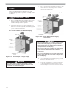
B. AUTOMATIC VENT DAMPER
INSTALLATION – GENERAL
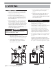
1. Do not use one vent damper to control two or more
heating appliances. See Figure 3.1.
2. Follow these and the installation instructions
included with the vent damper. Observe the cautions
and warnings that accompany all instructions.
3. Provide minimum 6 inch (152 mm) clearance
between automatic vent damper and combustible
construction. Increase clearance if required by vent
damper manufacturer’s instructions. Provide
adequate space for vent damper access and service.
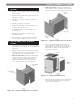
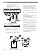
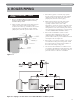
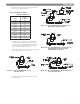
4. The automatic vent damper can be mounted directly
onto the draft hood outlet or in vent piping close to
the boiler.
See Figure 3.2 for installation with vent damper
mounted in vertical position. See Figure 3.3 for
installation with vent damper mounted in horizontal
position. Mount the unit to avoid excessive heat on
the operator or condensation drips into the operator.
Figure 3.1: Venting Multiple Appliances
Failure to provide adequate venting can result in
severe personal injury or death.
WARNING
3. VENTING