
Installation, Operation & Maintenance Manual


8
BOILER PLACEMENT & ASSEMBLY
11. If the sections do not draw together using the torque
specified above, the block must be separated and the
nipples replaced before reassembly is attempted.
12. The sections may alternatively be drawn together
using long 5/8" rods along with cast iron washers
through the nipple ports. Two large cast iron washers
(51163), two small cast iron washers (51165) and
two long 5/8" NPT rods are required (not provided).
Do not attempt to draw sections together without the
cast iron washers.
C. KNOCKDOWN BOILERS: ASSEMBLED
BLOCKS
1. If shipping pallet is still attached, move the
assembled block off of the pallet.
2. Move the assembled block to the location determined
in Chapter 1: Pre-installation. The location should
be on a level foundation as near to the chimney as
possible and centralized with respect to the heating
system.
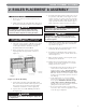
3. Attach the base front/rear insulated panels to the cast
iron block assembly as shown in Figure 2.2 using
3/8" carriage bolts and 3/8" hex nuts.
4. Attach the base lower rear panel to the cast iron block
assembly using 3/8" carriage bolts and hex nuts.
D. KNOCKDOWN BOILERS: CONTROL &
MANIFOLD ASSEMBLY
1. Remove the burner tray assembly from the burner
and controls carton.
2. Check burners to assure that they are seated
correctly in the burner tray rear support.
3. For Series 64™ boilers, assemble the 90° elbow and
return bend to the manifold assembly.
4. Remove the gas valve manifold components from
the burner tray and controls carton and connect
them to the burner manifold. Refer to Figure 5.2
through 5.5 in Section 5 for the specific Gas Train
Manifold Configuration.
5. Slide the burner tray under the cast iron block
assembly and attach to the end sections using the 1/4"
carriage bolts and nuts provided. (See Figure 2.2).
6. Attach the base burner access panel to the base front
panel assembly with two #10 x 1/2" sheet metal
screws (See Figure 2.2).
E. KNOCKDOWN BOILERS: FLUE
COLLECTOR ASSEMBLY
1. Remove the flue collector and ceramic blanket strip
insulation from burner and controls carton.
2. Lay the ceramic blanket strip on top of the boiler
using care not to block any flue passageways.
3. Insert the two 1/4"-20 carriage bolts provided with
boiler into the lugs on top of the boiler end sections
as shown in Figure 2.3.
4. Attach the flue collector to the bolts with the flat
washers and hex nuts provided. Tighten the nuts
snugly.
Figure 2.3: Flue Collector Attachment
Figure 2.2: Base Panel Attachment