
Installation, Operation & Maintenance Manual

12
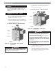
VENTING
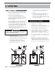
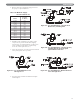
a. Orient the vent damper operator to facilitate
connection of the vent damper harness to
knockout on right side of boiler.
b. Orient vent damper direction arrow in direction
of vent gas flow. Direction arrow must be visible
from front of boiler.
C. BOILER REMOVAL FROM COMMON
VENTING SYSTEM
When an existing boiler is removed from a common
venting system, the common venting system is likely to
be too large for proper venting of the remaining
appliances connected to it.
At the time of removal of an existing boiler, follow these
steps with each appliance remaining connected to the
common venting system placed in operation, while the
other appliances remaining connected to the common
venting system are not in operation:
a. Seal any unused openings in the common venting
system.
b. Visually inspect the venting system for proper size
and horizontal pitch and determine there is no
blockage or restriction, leakage, corrosion and other
deficiencies which could cause an unsafe condition.
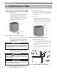
c. Insofar as is practical, close all building doors and
windows and all doors between the space in which
the appliances remaining connected to the common
venting system are located and other spaces of the
building. Turn on any clothes dryers and any
appliance not connected to common venting system.
Turn on any exhaust fans, such as range hoods and
bathroom exhausts, so they will operate at maximum
speed. Do not operate a summer exhaust fan. Close
fireplace dampers.
d. Place in operation the appliance being inspected.
Follow the lighting instructions. Adjust thermostat so
appliance will operate continuously.
e. Test for spillage at the draft hood relief opening after
5 minutes of main burner operation. Use the flame
of a match or candle, or smoke from a cigarette,
cigar, or pipe.
f. After it has been determined that each appliance
remaining connected to the common venting system
properly vents when tested as outlined above, return
doors, windows, exhaust fans, fireplace dampers and
any other gas-burning appliance to their previous
conditions of use.
g. Any improper operation of the common venting
system should be corrected so that the installation
conforms with the National Fuel Gas Code, ANSI
Z223.1/NFPA 54 or CAN/CGA B149 Installation
Codes. When resizing any portion of the common
venting system, the common venting system should
be resized to approach minimum size as determined
using the appropriate tables located in the chapter
“Sizing of Category I Venting Systems,” of the
National Fuel Gas Code, ANSI Z223.1/NFPA 54 or
CAN/CGA B149 Installation codes.
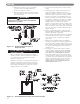
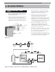
Figure 3.2: Venting with Vent Damper in
Vertical Position
Figure 3.3: Venting with Vent Damper in Horizontal Position
Damper must be in open position when appliance
main burner is operating.
CAUTION