
Installation, Operation & Maintenance Manual

13
BOILER PIPING
A. WATER BOILER PIPING – SINGLE
BOILER
1. Refer to the PB Heat Water Installation Survey and
Hydronics Institute Residential Hydronic Heating
Installation Design Guide.
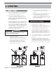
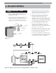
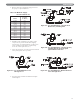
2. Figure 4.1 shows typical supply and return piping for
a boiler system. If the system expansion tank is
located on the boiler loop, it should be located on the
supply side of the boiler with the system circulator
pumping away from the expansion tank connection.
3. If the boiler is piped in a secondary loop separate
from the system expansion tank, the boiler circulator
should be located on the return side of the boiler
pumping away from the common piping.
4. Return water should not reach the boiler return
connection at less than 130°F under normal
operating conditions. If the system return
temperature is expected to be below 130°F the boiler
should be piped in a secondary loop with a bypass
arrangement to assure water returning to the boiler is
above 130°F. For more information on bypass piping
consult the PB Heat Water Installation Survey.
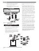
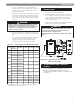
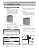
5. If the boiler and distribution system is used in
conjunction with a refrigeration system, pipe the
chilled medium in parallel with the boiler and
provide isolation valves to prevent chilled water form
entering the boiler. See Figure 4.2.
6. If the boiler is connected to a heating coil in a forced
air combination heating and cooling system, install
flow control valves to prevent gravity circulation of
the boiler water during cooling cycles.
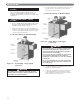
7. A hot water boiler installed above radiation level or
as required by the Authority having jurisdiction, must
be provided with a low water cut-off device either as
part of the boiler or at the time of installation.
4. BOILER PIPING
Figure 4.1
Figure 4.2: Piping to Isolate Boiler from Chilled Medium on Chiller Systems