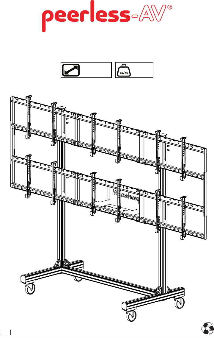
DS-C555-3X2 46" - 55" (117 - 140cm) MAX 600 lb (272 kg) ENG 1 2014-05-30 #:009-9084-2 (2014-07-15)
This page intentionally left blank.
WARNING Do not begin to install product until you have read and understood the instructions and warnings contained in this user guide. Always use an assistant or mechanical lifting equipment to safely lift and position equipment. This product must be installed onto flat, hard, level surface to prevent tipping. The cart or stand is not affixed or secured to the floor, and may therefore tip over and/or fall if screen and/or stand is shaken or hit. Displays must be removed before moving cart.
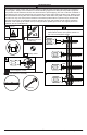
Parts (Before beginning, make sure you have all parts shown below).
L (1 ) M (1 ) computer cover N (2 ) computer shelf dual cross support O (4 ) locking tab P (4 ) cord bracket Q (2 ) cross support S (124) (4 ) Rplate M8 x 16mm connections U (24) cover clip Y (1 ) 5mm allen wrench V (14) W (4 ) M5 x 10mm Z (24) nylon shoulder washer T (68) M8 square nut X (1 ) M5 x 12mm AA (24) M6 x 12mm 5 1/4" power bit BB (1) 4mm allen wrench 2014-05-30 #:009-9084-2 (2014-07-15)
1 Repeat for each caster assembly.
2 Repeat for each base leg assembly.
3 Repeat for each base leg assembly. TIGHTEN CONNECTING HARDWARE 4 Repeat for each base support (x6).
5 TIGHTEN CONNECTING HARDWARE Repeat for each side (x2).
7 Repeat for each vertical support bracket (x4).
8 Repeat for each cross support assembly (x2).
9 Must install bottom row first. TIGHTEN HARDWARE (X2) TIGHTEN HARDWARE (X2) Cross supports must center on vertical leg supports.
10 Must install top row last. TIGHTEN HARDWARE (X2) TIGHTEN HARDWARE (X2) Cross supports must center on vertical leg supports.
11 J S (2) T (2) 14 2014-05-30 #:009-9084-2 (2014-07-15)
12 TIGHTEN CONNECTING HARDWARE O P OPTIONAL: Unlock wheels to move cart to desired location; Lock wheels before hanging screens.
13 Center adapter brackets vertically on back of screen. X .98" (25mm) 7.87" (200mm) 3.94" (100mm) 2.50" (63mm) 15.75" (400mm) X 2.50" (63mm) 0.
14-1 Must hang displays to bottom row first; Secure pin in "locked" position. "LOCKED" POSITION 14-2 Must hang displays on top row second; Secure pin in "locked" position. "LOCKED" POSITION 14-3 OPTIONAL: Insert M5 x 10mm type-F socket pin screws (V) to lock latches.
Display Adjustment IN OUT SIDE SIDE TILT BACKWARD SIDE TILT RIGHT TILT LEFT TOP SIDE UP TILT FORWARD TOP DOWN ROTATE LEFT 18 ROTATE RIGHT 2014-05-30 #:009-9084-2 (2014-07-15)
15 M 16 1/8" (3mm) M L V (2) TIGHTEN CONNECTING HARDWARE M 19 2014-05-30 #:009-9084-2 (2014-07-15)
17 U (4) C 20 2014-05-30 #:009-9084-2 (2014-07-15)
18 Route cables through cord brackets.
19 Display Removal Pull down on bracket cords and hold. Swing screen away from cart and lift to remove. 20 Remove displays from top row first.
21 Repeat step 19 to remove displays from bottom row last.
LIMITED FIVE-YEAR WARRANTY Peerless Industries, Inc. (“Peerless”) warrants to original end-users of Peerless® products will be free from defects in material and workmanship, under normal use, for a period of five years from the date of purchase by the original end-user (but in no case longer than six years after the date of the product's manufacture). At its option, Peerless will repair or replace, or refund the purchase price of, any product which fails to conform with this warranty.