
PureFire PFA-1 Interface Adaptor Installation, Operation, and Maintenance Manual


A. OVERVIEW
The PFA-1 Interface Adapter is designed to allow for
electronic interface between the P
UREFIRE main control
and other electronic devices.
1. Alarm Output and External Reset Input:
In the event of a blocking or locking error, the PFA-1
Interface adapter will provide a contact closure to
signal an external device (alarm bell, phone dialer,
etc.) of a problem.
2. Analog Input:
The PFA-1 Interface Adapter will accept an analog
input of 0-10VDC. This analog signal can be used to
control Setpoint Temperature or Gas Input Rate. This
signal is typically provided by a Building Automation
system.
For Cascade installations, only one PFA-1 Adapter is
required per cascade system to control the System
Setpoint. If Analog control of Gas Input is required,
one InterFace Adapter is required per boiler.
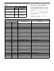
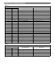
3. Modbus Interface:
The PFA-1 Interface Adapter allows external access
to boiler status information using MODBUS RTU
protocol. This provides remote access to
Temperatures, Operating Status and Error
Information as applicable.
One PFA-1 control is required for each boiler to
which Modbus communication is desired. In a
multiple boiler cascade control configuration, each
boiler must be equipped with a PFA-1 Interface
Control to allow full communication.
a. Temperatures
: Supply, Return, DHW and Vent
Temperatures can be monitored. In addition, the
System Temperature in a multiple boiler
(cascade) system can be accessed.
b. Operating Status
: The boiler status can be
monitored to determine if the boiler is in
Standby, Prepurge, Ignition, Firing, Postpurge or
Alarm conditions. It can also indicate if it is
satisfying a central heating (CH) or domestic hot
water (DHW) demand.
c. Error Information
: If the boiler is in a lockout or
blocking error, the interface will allow access to
the error code.
B. PRE-INSTALLATION
1. PF-210 & PF-399 boilers come equipped with pre-
wired harnesses to connect to the PFA-1 Interface
Adapter. If modbus is required, two additional wires
(provided with kit) must be connected as shown
below.
2. To connect to the PF-50, PF-80, PF-110 or PF-140
boilers, harnesses (supplied with the PFA-1 Interface
Adapter) are required.
3. For stand alone boilers, one PFA-1 Interface Adapter is
required for each unit. For multiple boiler installations,
one PFA-1 Interface Adapter will provide Alarm
information, Setpoint control, and/or Modbus interface
for the system. If individual boiler information is
required, an interface unit is required for each of them.
4. The PFA-1 Interface Adapter is designed to fit within
the P
UREFIRE boiler jacket. This manual will provide
suggested mounting locations and wiring diagrams.
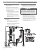
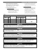
C. INSTALLATION
1. Figure 1 shows the suggested mounting location for
the PFA-1 Interface Adapter on the PF-50, PF-80,
PF-110 and PF-140 boilers.
• These boilers require a PFA-1 Harness Adapter
Kit (provided) to connect to the boiler.
2. Figure 2 shows the suggested mounting location for
the PFA-1 Interface Adapter on the PF-210 and PF-
399 boilers.
• These boilers come with pre-wired harnesses for
connection of the adapter. If modbus is required,
two additional wires (provided with kit) must be
connected as shown below.
3. Attach PFA-1 Adapter to jacket panel using adhesive-
backed Velcro provided with the kit.
Peerless
®
PUREFIRE
®
PFA-1 Interface Adapter
Installation, Operation and Maintenance Manual
Figure 1
Figure 2
1