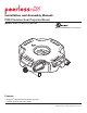
Installation and Assembly Manual: PRG Precision Gear Projector Mount Models: PRG-1, PRG-1S, PRG-1W Max UL Load Capacity: 50 lb (22.68 kg) Features: • ImageLockTM alignment prevents picture sag or drift • Exclusive aluminum track quick release 2300 White Oak Circle • Aurora, Il 60502 • (800) 865-2112 • Fax: (800) 359-6500 • www.peerlessmounts.
NOTE: Read entire instruction sheet before you start installation and assembly. WARNING • Do not begin to install your Peerless product until you have read and understood the instructions and warnings contained in this Installation Sheet. If you have any questions regarding any of the instructions or warnings, please call Peerless customer care at 1-800-865-2112.
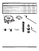
Before you start check the parts list to insure all of the parts shown are included. Parts List Description A projector mount assembly B 4 mm security allen wrench C #10-32 x 3/8" serrated washer head socket pin screw D #10-32 x 1/4" socket pin screw E flat washer F #14 x 2-1/2 phillips hex head wood screw G concrete anchor H 2 mm security allen wrench I connection block Qty.
Installation to Extension Column / Ceiling Plate 1 NOTE: Refer to accompanying instructions with ceiling plates (sold separately) for installing these models to ceiling. Screw projector mount assembly (A) onto extension column as shown in figure 1.1. Tighten swivel stop screw against extension column, flush mount tube or reducer using 4mm security allen wrench (B) as shown in figure 1.2.
Installation To Wood Joist Ceilings WARNING • Installer must verify that the supporting surface will safely support the combined load of the equipment and all attached hardware and components. • Tighten wood screws so that projector mount assembly is firmly attached, but do not overtighten. Overtightening can damage the screws, greatly reducing their holding power. • Never tighten in excess of 80 in. • lb (9 N.M.). • Make sure that mounting screws are anchored into the center of the stud.
Installation to Concrete Ceilings WARNING • Concrete must be 2000 psi density minimum. Lighter density concrete may not hold concrete anchor. • Make sure that the supporting surface will safely support the combined load of the equipment and all attached hardware and components. 3 Place projector mount assembly (A) on ceiling as a template and mark the center of the two mounting holes. Drill two 5/16" (8mm) dia. holes to a minimum depth of 2-1/2" (64mm).
Installation to Threaded Rod (Not evaluated by UL - Professional installation only) 4 Thread two 1/4-20 hex thin nylon-insert locknuts (not included) on two 1/4-20 threaded rods (not included) to the desired height of projector mount assembly. Attach projector mount assembly (A) to the two 1/4-20 threaded rods using two 1/4-20 hex thin nylon-insert locknuts as shown in figure 4.1 or figure 4.2.
Attaching Adapter Plate to Projector CAUTION I fig. 5.1 • It is the responsibility of the installer to ensure that the projector is properly ventilated. 5 SHOULDER NOTCH INDICATES FRONT OF PROJECTOR Installing Dedicated PAP Series Adapter Plate (sold separately) DEDICATED ADAPTER PLATE (SOLD SEPARATELY) NOTE: The projector dedicated adapter plate you are installing may differ in appearance from the sample illustrated in figure 5.1.
Attaching Adapter Plate to Projector Mount WARNING • Do not lift more weight than you can handle. Use additional man power or mechanical lifting equipment to safely handle placement of the projector. 6 Slide connection block (I) with projector into projector mount assembly (A) as shown. Tighten captive screw to secure projector to projector mount assembly (A).
Cable Management 8 fig. 8.1 To make an opening to route cables through projector mount assembly, adjust projector mount assembly to full upward tilt position by turning knob for tilt adjustment as shown in figure 8.2. Left or right roll position can be adjusted if more space is required. CABLES WITH COMBINATION OF VGA CONNECTOR AND RCA PLUGS NOTE: Be certain tamper resistant screws are not engaged before making adjustments (see step 9). Route cables through top of extension column as shown in figure 8.
Projector Alignment To adjust yaw (swivel) for threaded rod mounting applications: Loosen locknuts on threaded rods (step 4), until projector mount can be rotated. Rotate mount to desired position and retighten locknuts. 9 To adjust yaw (swivel) for extension column applications: Loosen screw on projector mount assembly (A) indicated below until projector mount can be rotated. Rotate mount to desired position and retighten screw.
PRG Series Projector Mount Accessories Ceiling Plates Escutcheon Ring Unistrut® Adapter Truss Ceiling Adapter MODEL: ACC 557* MAX LOAD: 250 lbs. (113.4 kg.) COLOR: Black MODEL: ACC 640 MODEL: ACC 550 MAX LOAD: 250 lbs. (113.4 kg.
PRG Series Projector Mount Accessories Cord Management • Includes, four, 2' sections • Designed to externally route cords along the outside of an 1/2" extension column • Sections can be stacked to create longer lengths or cut to desired length Cord Wrap MODELS: ACC 852(W)(S)* COLOR: Black, White, or Silver Extension Columns Fixed Length 1 1/2" Extension Columns Adjustable Length 1 1/2" Extension Columns COLOR: Black COLOR: Black MODEL EXT 006 EXT 018 EXT 101 EXT 102 EXT 103 EXT 104 EXT 105 EXT 106 EXT