
Specifications

ISSUED:10-23-07 SHEET #: 087-9016-1
Visit the Peerless Web Site at www.peerlessmounts.com For customer care call 1-800-729-0307 or 708-865-8870.
6 of 18
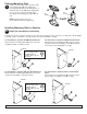
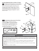
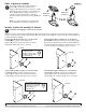
For Attachment to Drywall surface
3-2
Use mounting plate (A) as a template to mark
the two mounting holes. NOTE: In wall
mounting applications position mounting holes
in a vertical pattern. Drill two 5/16" (8 mm) dia.
holes through drywall. Insert anchors (O) in
holes flush with drywall as shown in figure 3.4.
Place mounting plate over anchors and secure
with two #12 x 1-3/4" self tapping screws (N).
fig. 3.4
fig. 3.5
fig. 3.6
DRYWALL
DRYW
ALL
4
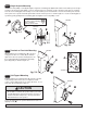
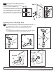
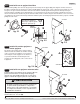
Installing Arms to Mounting Plate
Insert arm (C) or extension arm (D) onto mounting plate attached to
surface as shown in figure 4.1 or 4.2. Extension arm can be used with arm
as shown in figure 4.3. Tighten set screws with allen wrench (P).
NOTE: Extension arm is not recommended with wall mounted
applications.
Insert mounting plate (A or B) attached on speaker into arm (C). Tighten
set screw with allen wrench (P) as shown in figure 4.4 or 4.5.
SET SCREW
SET SCREW
SET SCREW
fig. 4.1
fig. 4.2
fig. 4.3
fig. 4.4
fig. 4.5
SET SCREW
SET SCREW
© 2007, Peerless Industries, Inc. All rights reserved.
All other brand and product names are trademarks or registered trademarks of their respective owners.
O
DRYWALL
N
A
O
A
O
N
A
D
C
A
C
A
C
C
A or B
A or B
C