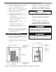
Series WB90™ Oil Boilers As an ENERGY STAR® Partner, PB Heat, LLC has determined that this product meets the ENERGY STAR guidelines for energy efficiency.
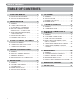
TABLE OF CONTENTS TABLE OF CONTENTS USING THIS MANUAL 1 A. INSTALLATION SEQUENCE . . . . . . . . . . . . .1 B. SPECIAL ATTENTION BOXES . . . . . . . . . . . .1 1. PREINSTALLATION 2 A. GENERAL . . . . . . . . . . . . . . . . . . . . . . . . . . . .2 B. CODES & REGULATIONS . . . . . . . . . . . . . . .2 C. ACCESSIBILITY CLEARANCES . . . . . . . . . . .3 D. AIR FOR COMBUSTION AND VENTILATION – OUTDOOR AIR . . . . . . . . . .4 E. APPROVED VENTING/AIR INLET CONFIGURATIONS . . . . . . . . . . . . . . . . . . . .
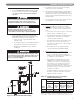
USING THIS MANUAL USING THIS MANUAL A. INSTALLATION SEQUENCE Follow the installation instructions provided in this manual in the order shown. The order of these instructions has been set in order to provide the installer with a logical sequence of steps that will minimize potential interferences and maximize safety during boiler installation. DANGER Indicates a condition or hazard which will cause severe personal injury, death or major property damage. WARNING B.
PREINSTALLATION 1. PREINSTALLATION NOTICE In accordance with Section 325 (f) (3) of the Energy Policy and Conservation Act, this boiler is equipped with a feature that saves energy by reducing the boiler water temperature as the heating load decreases. This feature is equipped with an override which is provided primarily to permit the use of an external energy management system that serves the same function.
PREINSTALLATION 3. This boiler exceeds the requirements of the United States Department of Energy for energy efficient operation and is ENERGY STAR® compliant. 4. Installation and repairs are to be performed in strict accordance with the requirements for state and local regulating agencies and codes dealing with boiler and oil-fired appliance installations. 5. In the absence of local requirements the following codes/standards should be followed: a.
PREINSTALLATION D. AIR FOR COMBUSTION AND VENTILATION – OUTDOOR AIR 1. The WB90™ boiler is designed to allow combustion air to be piped directly to the appliance from outside the building (sealed combustion). To do this, an optional Combustion Air Inlet Kit (54557) is available from your PB Heat, LLC distributor. 2.
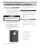
BOILER PLACEMENT & ASSEMBLY 2. BOILER PLACEMENT & ASSEMBLY A. BOILER PLACEMENT 1. Provide a level foundation, located as close as possible to the center of the heating system. 2. It is a good idea to remove the boiler jacket wrapper, top panel and plastic front panels before moving the boiler down steps or through doorways. This reduces the chance of damaging the jacket panels. 3. Do not attempt to move the boiler by pushing or pulling on the plastic front panels.
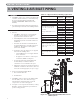
VENTING & AIR INLET PIPING 3. VENTING & AIR INLET PIPING A. GENERAL 1. The WB90™ boiler can be vented vertically through a stainless steel lined chimney or horizontally using the approved Sidewall Vent Termination Kit (DuraVent 47PVP-OKA / PB Heat Stock Code #54086). Table 3.
VENTING & AIR INLET PIPING C. SIDEWALL VENTING 1. Use the CONDENSATE DRAIN TEE supplied with the boiler to attach venting to the boiler. DO NOT USE THE VENT RESTRICTOR FOR SIDEWALL VENTING. NOTICE Do not use the vent restrictor supplied with the boiler for sidewall venting. This restrictor will prevent adequate combustion air from entering the boiler. 3. The exhaust and inlet air piping for horizontally vented boilers must be 4" diameter. 4.
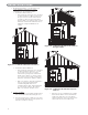
VENTING & AIR INLET PIPING 3. Residential Construction – Confined Space: For boilers installed in confined spaces, air for combustion is to be provided as follows: a. Combustion Air from Indoors: • Two permanent openings are to be provided as shown in Figure 3.3. One near the top of the space and one near the bottom. Each opening is to have free area not less than shown in Table 3.2, column 2. Each opening shall freely communicate with interior areas which have adequate infiltration from outside. Figure 3.
VENTING & AIR INLET PIPING 5. Special Conditions: If the boiler is located in areas where exhaust fans, clothes dryers, direct-fired water heaters or fireplaces can create conditions for unsatisfactory combustion or venting, special provisions must be made. 6. Specially Engineered Installations: The size of combustion air openings shown in this section may not apply to specially engineered systems. These systems are to be designed to ensure an adequate supply of air for combustion and ventilation.
WATER PIPING 4. WATER PIPING A. GENERAL CAUTION The boiler return pipe MUST be piped to the rear 1-1/4" tapping of the WB90™ boiler to prevent flue gas condensation which may damage the cast iron sections. Failure to comply may void the warranty. 1. Follow these instructions closely in order to be sure that the boiler operates as it is intended. Water piping is extremely important to the system operation. 2. Size water supply and return piping in accordance with system requirements. 3.
WATER PIPING 6. Back Flow Preventer: A back flow preventer (check valve) is required by some jurisdictions to prevent water in the hydronic system from backing up into the city water supply if the supply pressure drops below that of the heating system. This is especially important on systems in which glycol solution is used as a heating medium. 7. Pressure Relief Valve: The boiler pressure relief valve is shipped separately for field installation.
Figure 4.
WATER PIPING C. SYSTEM PIPING 1. Figure 4.3 shows the recommended piping for the WB90™ boiler. It is extremely important that the boiler is piped primary/secondary (as shown) to prevent damage to the boiler due to condensation. 2. The DHW zone is piped from the primary loop in parallel with the central heating (CH) zones. It should be piped as close to the boiler as possible since it should be the hottest zone. E. SPECIAL APPLICATIONS 1.
OIL BURNER 5. OIL BURNER CAUTION A. GENERAL 1. The WB90™ boiler is available exclusively with the H2L Oil burner from Carlin Combustion Technologies, Inc. 2. The burner is UL Listed for commercial standard No. 1 or No.2 heating oil meeting the ASTM D396 fuel oil specification. Do not use compression fittings for oil supply lines. Do not use copper sweat fittings with oil piping. Air leaking into the oil supply system may cause erratic burner operation and/or burner lockout.
OIL BURNER 11. Fuel unit bypass plug: The boiler is shipped with the fuel unit (oil pump) bypass plug NOT installed. The bypass plug is shipped loose for use only when a two-line oil supply system is used. Operating with the bypass plug in place when installed in a one-line oil supply system will damage the fuel unit and may lead to oil leakage resulting in a fire hazard. WARNING Do not install the bypass plug when operating the burner in a one-line oil supply system.
OIL BURNER • If the head position bar is correct, loosen the air band clamping screw and rotate the air band slightly to increase or decrease air flow. 4. Adjust High Fire Combustion: a. Be sure the service switch is ON and initiate a call for heat. • Adjust the air band (or air shutter if an air boot is used) for the highest CO2 (Lowest O2) possible with 0 smoke on the Bacharach scale. Do not exceed 13.0% CO2 (3.3% minimum O2). b.
OIL BURNER WARNING h. Use the smoke tester to sample the smoke in the vent. DO NOT attempt to set up the burner without using test instruments. Visual inspection cannot be trusted to assure proper operation. Failure to check and adjust combustion using combustion test instruments may result in severe personal injury, death and/or major property damage. • Use the smoke tester in accordance with the manufacturers’ instructions. • The smoke sample should be zero (0) on the Bacharach scale. f.
CONDENSATE REMOVAL 6. CONDENSATE REMOVAL A. GENERAL 1. The disposal of all condensate into public sewage systems is to be in accordance with local codes and regulations. In the absence of such codes, follow these instructions. 2. Proper piping and removal of condensation from the vent system is critical to the operation of the WB90™ boiler. 3. Depending on several factors, the pH of condensate from oil-fired appliances may be as low as 2.0.
ELECTRICAL CONNECTIONS & CONTROLS 7. ELECTRICAL CONNECTIONS & CONTROLS A. GENERAL The WB90™ boiler is to be wired in accordance with local codes and regulations as defined by the Authority having jurisdiction. In the absence of such local codes, this appliance is to be wired in accordance with the latest edition of the National Electrical Code, ANSI/NFPA 70. B. CUSTOMER CONNECTIONS 1.
ELECTRICAL CONNECTIONS & CONTROLS Figure 7.
ELECTRICAL CONNECTIONS & CONTROLS C. ZONE CIRCULATOR WIRING 1. Wiring for a typical zone circulator relay is shown in Figure 7.3. a. Power from WB90™ terminal #9 supplies 120 volts to terminal ZC on the zone panel. This configuration uses the neutral from the zone relay power supply so no neutral is necessary from terminal #10. b. Remove the jumper between ZC and H. c. In this configuration, the power for the zone circulators is provide by the boiler output.
ELECTRICAL CONNECTIONS & CONTROLS D. RESET LIMIT / LOW WATER CUTOFF (LWCO) CONTROL 1. The WB90™ comes equipped with the HydroStat 3250-H2L which is specifically designed to: a. Provide low water cutoff (LWCO) protection b. Operate as a reset-type temperature limit control • Thermal Targeting (Default) • Outdoor Reset (Optional) c. Provide 2-stage operation of the H2L burner d. Accept thermostat input for central heat (CH) [24 VAC Circuit] e.
ELECTRICAL CONNECTIONS & CONTROLS b. The feature to be set is selected by turning the HI TEMP dial. c. If the boiler provides adequate heat at the value chosen, an opportunity for greater fuel savings may be achieved by selecting a higher setting. • This dial will scroll through the available options from 1 – 7 or dEF. 5. Zone/Indirect (I/Z) Switch: a. When installing the WB90™ with an indirect water heater, the Z/I switch should be set to the “I” position.
ELECTRICAL CONNECTIONS & CONTROLS 8.
ELECTRICAL CONNECTIONS & CONTROLS E. CARLIN 65000 FIRING RATE CONTROL 1. Functions: a. Input: Call for Heat from Hydrostat 3250-H2L Control b. Input: Firing Rate from HydroStat 3250-H2L Control c. Input: Oil Temperature Feedback from Sensor d. Output: Activates Oil Heater for LO/HI Fire e. Output: Call for Heat to 60200 Primary Ignition Control f. Output: Provides Diagnostic Information in Fault Condition 2. Indicator Lights: a. HEATER – On when Oil Heater is Active b.
ELECTRICAL CONNECTIONS & CONTROLS Figure 7.
MAINTENANCE 8. MAINTENANCE WARNING Product Safety Information Refractory Ceramic Fiber Product This appliance contains materials made from refractory ceramic fibers (RCF). Airborne RCF fibers, when inhaled, have been classified by the International Agency for Research on Cancer (IARC), as a possible carcinogen to humans. After the RCF materials have been exposed to temperatures above 1800°F, they can change into crystalline silica, which has been classified by the IARC as carcinogenic to humans.
MAINTENANCE 9. Remove scale or soot from the combustion chamber area by vacuum cleaning or other available means. A. GENERAL 1. The entire heating system, including the boiler, burner and venting system, MUST be inspected at least once per year by a qualified heating service professional. 2. It is extremely important to follow these instructions to prevent damage to the boiler and/or building structure. B. CLEANING HEATING SURFACES 1.
MAINTENANCE D. WATERSIDE INSPECTION 1. Connect a suitable drain hose to the boiler drain valve. Have a 5 gallon bucket available to catch boiler water. 2. Be sure that the system temperature is below 125°F before draining water from the system. WARNING Water in excess of 125°F can cause severe burns instantly. DO NOT drain water in excess of 125°F from the boiler. Failure to comply may cause severe personal injury or death. 3. Drain water from the boiler into the bucket.
DIMENSIONS & RATINGS 9. DIMENSIONS & RATINGS Figure 9.1: Dimensional Drawing – WB90™ Table 9.1: Series WB90™ Boiler Dimensions SERIES WB90™ BOILER DIMENSIONS Boiler Model Number Jacket Depth “A” Jacket Width “B” Jacket Height “C” Vent Size Diameter “D” WB90-03 WB90-04 18-3/8" 22-3/8" 23-5/8" 23-5/8" 39-1/4" 39-1/4" 4" 4" Table 9.2: Series WB90™ Boiler Ratings SERIES WB90™ BOILER RATINGS Series WB90™ Boiler Model Number WB90-03 WB90-04 Input Rate¹ Maximum GPH 0.90 1.
This page intentionally left blank.
REPAIR PARTS 10. REPAIR PARTS Repair parts are available from your local PB Heat, LLC distributor or from Parts To Your Door at 1 (610) 916-5380 (www.partstoyourdoor.com). Note: Remember to include the boiler model number and serial number when ordering parts. Figure 10.
REPAIR PARTS Table 10.
REPAIR PARTS Figure 10.
REPAIR PARTS Table 10.
REPAIR PARTS Table 10.
Series WB90™ Oil Boilers Installation, Operation & Maintenance Manual TO THE INSTALLER: This manual is the property of the owner and must be affixed near the boiler for future reference. TO THE OWNER: This boiler should be inspected annually by a Qualified Service Agency. PB HEAT, LLC 131 S. CHURCH STREET • BALLY, PA 19503 ©2015 PB Heat, LLC. All rights reserved. PP8127 R1 (7/15-1M) Printed in U.S.A.