Installation and Assembly: Wireless TV Cart for 47" to 65" Flat Panel Displays Models: WL-SR560M-200 Max Load Capacity: 150 lb (68 kg) screen 50 lb (22.7 kg) per shelf 2300 White Oak Circle • Aurora, Il 60502 • (800) 865-2112 • Fax: (800) 359-6500 • www.peerless-av.
NOTE: Read entire instruction sheet before you start installation and assembly. WARNING • Do not begin to install your Peerless product until you have read and understood the instructions and warnings contained in this Installation Sheet. If you have any questions regarding any of the instructions or warnings, for US customers please call Peerless customer care at 1-800-865-2112, for all international customers, please contact your local distributor.
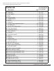
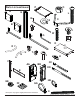
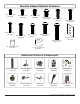
Before you begin, make sure all parts shown are included with your product. Parts may appear slightly different than illustrated. Parts List A B C D E F G H I J L M N O P Q R S T U V W X Z AA BB CC DD EE FF GG HH II JJ WL-SR560M-200 Qty.
Parts List continued A P O G L N C X B I JJ M W Q Z J D R U T S V F AA BB H CC DD E EE HH FF GG Some parts may appear slightly different than illustrated.
Security Adapter Bracket Fasteners M4 x 12 mm (6) 510-1079 M5 x 12 mm (4) 520-1064 M4 x 25 mm (4) 510-1082 M6 x 30 mm (4) 520-1067 M6 x 12 mm (4) 520-1050 M6 x 25 mm (4) 520-1211 M8 x 15 mm (6) 520-1068 M6 x 20 mm (4) 520-9554 M5 x 25 mm (4) 520-1122 M8 x 25 mm (4) 520-1101 multi-washer (6) 580-1036 M8 x 40 mm (4) 520-1152 I.D. .22" (5.6 mm) (4) 540-1057 I.D. .34" (8.7 mm ) (4) 540-1059 Additional Wireless Components Quick Start Guide PRO WIRELESS MULTIMEDIA KIT ® READY 2 Minutes Model No.
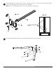
1 Insert right leg (S) into base housing (D) as shown in fig. 1.1. Then align holes in right leg with holes in base housing (D). Fasten base housing to right leg using two 3/8-16 x 1.5" bolts (W) and two joint connectors (V). Tighten using 3/16" allen wrench (Z) and 7/32" allen wrench (M) as shown in fig.1.2. NOTE: Left and right legs can be identified by looking at the cart from the front. Repeat for left side with left leg (R). fig. 1.1 fig. 1.
3 Attach upright (G) to base (D), as shown in fig 3.1 using three 3/8-16 x 2.5" socket screws (L) and M10 x .402ID lock washers (X). Tighten screws using 7/32" allen wrench (M). NOTE: Be sure cord management holes are in the configuration shown in fig 3.2. fig. 3.1 fig. 3.2 G CORD MANAGEMENT HOLES D X L 4 Loosely attach four 1/4-20 x 12 mm screws (I) and 1/4-20 nuts (J) to shelf support (C).
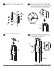
5 Slide shelf support (C) onto upright (G) so that 1/4-20 nuts (J) slide into slots of upright (G) as shown in figure 5.1 and detail 1. Slide shelf support to desired height, level, then tighten 1/4-20 x 12mm screws (I) using 4 mm allen wrench (N). NOTE: MAXIMUM OF TWO SHELVES Max height of top shelf is 34" from base. Max height of second shelf is 28" from base. C J G SLOT DETAIL 1 fig. 5.
Attaching Metal Shelf 6 Attach shelf pan (P) to shelf support (C) using six 8/32 nylock nuts (O) as shown below. Use an adjustable wrench to tighten six 8/32 nylock nuts (O). WARNING • This shelf is intended for use with equipment weighing NO more than 50 lbs. (22.7 kg) that fits evenly accross the surface of shelf pan (P). Use with other equipment may result in instability and cause personal injury or property damage.
7 Loosely attach six 1/4-20 x 12 mm screws (I) and 1/4-20 nuts (J) to screen mount bracket (A). Slide screen mount bracket (A) onto upright (G) so that 1/4-20 nuts (J) slide into slots of upright (G) as shown in figure 8.1 and detail 2. Slide screen mount bracket to desired position, level, then tighten 1/4-20 x 12 mm screws (I) using 4 mm allen wrench (N). 8 A J J I G I DETAIL 2 SLOT A G fig. 8.1 9 Snap top cover (H) onto upright (G).
Wireless Receiver and Power Enclosure Installation NOTE: For mounting patterns smaller than VESA 400, use large enclosure mounting bracket (DD). 11 NOTE: The Wireless Receiver Assembly (AA) and Power Module Assembly (BB) position can be interchanged based on the display’s connector panel location. Install Wireless Receiver Assembly on the side closest to the connector panel.
Installing Adapter Brackets to Universal Plate WARNING • Tighten screws so adapter brackets are firmly attached. Do not tighten with excessive force. Overtightening can cause stress damage to screws, greatly reducing their holding power and possibly causing screw heads to become detached. Tighten to 40 in. • lb (4.5 N.M.) maximum torque.
-1 Begin with longer length screw, hand thread through multi-washer, adapter bracket and spacer in that order into screen as shown below. Screw must make at least three full turns into the mounting hole and fit snug into place. Do not over tighten. If screw cannot make three full turns into the screen, select a shorter length screw from the baffled fastener pack. Repeat for remaining mounting holes, level brackets and tighten screws. fig. 13.
Attaching Universal Adapter Plate 14 Attach Universal Plate (E) to hook plate (B) using four M10 x 15 mm socket screws (JJ). Tighten screws using 6 mm allen wrench (Q). 15 Attach hook plate (B) to screen mount bracket (A). B E B A JJ 16 Insert two 1/4-20 x 12 mm screws (I) into holes indicated below for desired screen orientation. Tighten all screws using 4 mm allen wrench (N).
Wireless Receiver Assembly and Power Module Assembly Setup 17 Remove the two #8 screws securing the cover of the wireless receiver assembly (AA) as shown in detail 4. Open the enclosure to expose the wireless receiver and IR unit. Remove the M5 x 10mm phillips screws and open the power module assembly (BB) as shown in detail 5. M5 X 10mm SCREWS BB AA #8 SCREW DETAIL 4 18 DETAIL 5 Untie the wireless receiver power adapter cord and route as shown below.
19 Locate the IR receiver inside of the wireless receiver enclosure shown in figure 19.1. Remove the tie from the cable and position the IR receiver on the display within line of sight of your remote as shown in figure 19.2. Remove the adhesive backing from the IR receiver eye and attach to the display. Coil up the excess cord near the wireless receiver enclosure (AA) and secure with a cable tie (HH). Store the coiled cord back inside of the enclosure. fig. 19.2 IR RECIEVER IR RECIEVER 20 fig. 19.
21 Install the cable tie anchor (FF) onto the inside back wall of the power enclosure (BB). Remove the adhesive backing from the anchor and press into place in the area shown. 22 FF Plug the power cord from your display into the triple tap grounded outlet as shown. Coil up the excess cord and secure with a cable tie (GG), inserting it through the cable tie anchor (FF) and around the coiled cord.
Mounting and Removing Flat Panel Screen WARNING • Always use an assistant or mechanical lifting equipment to safely lift and position the plasma television. 27 Hook adapter brackets (F) onto universal plate (E), then slowly swing screen in as shown. Turn screws of adapter plate (F) clockwise at least six times to prevent screen from being removed as shown in detail 7. NOTE: Tighten using 4 mm allen wrench (N). Screen can be adjusted horizontally if desired.
LIMITED WARRANTY Peerless Industries, Inc. (“Peerless-AV®”) warrants to original end-users of Peerless-AV® products that Peerless-AV® products will be free from defects in material and workmanship, under normal use, for the periods listed below, from the date of purchase by the original end-user. At its option, Peerless-AV® will repair or replace with new or refurbished products or parts, or refund the purchase price of any Peerless-AV® product which fails to conform with this warranty.