® Installation/Operation 100 Series Camclosure® Integrated Camera System C2407M-G (5/03) Pelco • 3500 Pelco Way • Clovis, CA 93612-5699 USA • www.pelco.
[2] Pelco Manual C2407M-G (5/03)
CONTENTS Section Page IMPORTANT SAFEGUARDS AND WARNINGS ..................................................................................... 4 DESCRIPTION ........................................................................................................................................ 4 INSTALLATION ........................................................................................................................................ 4 INSTALL BASE ..................................................
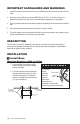
IMPORTANT SAFEGUARDS AND WARNINGS 1. Installation and servicing should be done only by qualified service personnel and conform to all local codes. 2. Unless the unit is specifically marked as a NEMA Type 3, 3R, 3S, 4, 4X, 6 or 6P enclosure, it is designed for indoor use only and must not be installed where exposed to rain and moisture. 3. Use only installation methods and materials capable of supporting four times the maximum specified load. 4.
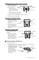
Mounting Directly to Concrete Wall or Ceiling 1. Attach the base to the wall or ceiling (hardware not supplied). MOUNTING 2. Do one of the following: HARDWARE (NOT SUPPLIED) a. Not Using Side Conduit Opening - Verify the set screw and side conduit cover are tight. OR b. Using Conduit to Side Opening - Loosen the set screw and remove the conduit plug. CONCRETE WALL OR CEILING BASE CONDUIT PLUG SET SCREW 3. Install a 3/4-inch (1.91 cm) conduit fitting and tighten the set screw. 4.
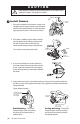
CAUTION Heater elements could be hot! When camera power is on, use caution when adjusting the camera. This applies to all models. 3 Install Camera HEATER BOARD 1. Some indoor installations do not require a heater. If the installation does not require a heater, remove the heater board from the camera assembly. To remove the heater apply pressure and press on the corner of the board. 2. If the heater is installed, plug the heater connector from the camera into the mating connector inside the base.
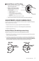
4 Install Dome and Trim Ring 1. Align the screw holes in the trim ring with those in the camclosure base. ADJUSTMENT GROOVE DOME LINER 2. Domes with Liners (only) – Position the viewing window over the LOOSEN SCREWS lens of the camera. a. Loosen the three Phillip screws located in the dome. b. Insert the blade of a standard screwdriver in one of the adjustment grooves. Move dome into position. c. Tighten the three Phillip screws to lock liner in place. 3.
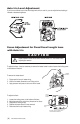
Auto Iris Level Adjustment If you have a varifocal lens or fixed focal length lens with an auto iris, you can adjust the level setting to increase or decrease brightness. Focus Adjustment for Fixed Focal Length Lens with Auto Iris CAUTION Heater elements could be hot! When camera power is on, use caution when adjusting the camera. To adjust the focus, it may be necessary to remove the heater board in order to loosen the locking screw on the bottom of the lens. HEATER BOARD To remove the heater board: 1.
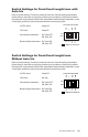
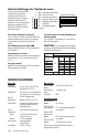
Switch Settings for Fixed Focal Length Lens with Auto Iris Refer to the switch drawing. The switch is located next to the lens. Automatic backlight compensation (factory setting) is used under varying lighting conditions (such as outdoors) or fixed lighting conditions where there are no bright spots that darken other picture details. Manual backlight compensation is used in fixed lighting conditions to optimize the picture detail when there are bright spots.
The high resolution camera with varifocal lens and auto iris is configured at the factory for optimal performance in lighting conditions where auto iris is required. It is also configured with the shutter speed set at 1/60 (NTSC) or 1/50 (PAL) and AGC set at 6 dB of gain.
Regulatory Notices FCC Class A (monochrome, EIA and CCIR cameras – except auto iris models) This equipment has been tested and found to comply with the limits of a Class A digital device, pursuant to part 15 of the FCC rules. These limits are designed to provide reasonable protection against harmful interference when the equipment is operated in a commercial environment.
PRODUCT WARRANTY AND RETURN INFORMATION WARRANTY Pelco will repair or replace, without charge, any merchandise proved defective in material or workmanship for a period of one year after the date of shipment. Exceptions to this warranty are as noted below: • Five years on FT/FR8000 Series fiber optic products. • Three years on Genex® Series products (multiplexers, server, and keyboard).