
User's Manual


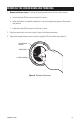
Table Of Contents
- List of Illustrations
- 1 Installation Directly to a Wall/Ceiling
- 2 Installation Directly to a Concrete Wall/Ceiling
- 3 Installation on a 4S Electrical Box
- 4 Mounting to a Plaster Ring
- 5 Terminal Block for Input Power
- 6 Heater Jumper and Camera Connector Locations
- 7 Default Switch Settings and Location of Camera Adjustments
- 8 Window Adjustment
- Contents
- Important Safeguards and Warnings
- REGULATORY NOTICES
- WELCOME
- INSTALL THE BACK BOX
- Remove the Lower Dome
- INSTALL THE BACK BOX
- Attach Directly to a Wall/Ceiling
- Attach Directly to Concrete Wall/Ceiling
- Attach to a 4S Electrical Box
- Mount to a Plaster Ring
- Connect Power Wires
- INSTALL THE CAMERA MODULE
- Check HEATER Jumper
- INSTALL AND POSITION the Camera
- Make Camera Settings
- Zoom/Focus
- Digital Slow Shutter (DSS)
- AGC (Automatic Gain Control)
- BLC (Back Light CompensatioN)
- Vertical Phase Adjustment (24 VAC Operation Only)
- How to Adjust the Phase Control
- VARIFOCAL LENS AUTO IRIS LEVEL ADJUSTMENT
- REINSTALL THE lower DOME AND TRIM RING
- SPECIFICATIONS
- WARRANTY AND RETURN INFORMATION
C2460M-A (7/03) 13
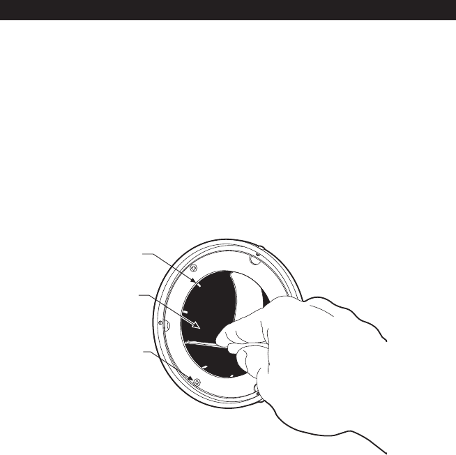
Figure 8. Window Adjustment
REINSTALL THE LOWER DOME AND TRIM RING
1. Domes with Liners (only) – Position the viewing window over the lens of the camera.
a. Loosen the three Phillip screws located in the dome.
b. Insert the blade of a standard screwdriver in one of the adjustment grooves. Move dome
into position.
c. Tighten the three Phillip screws to lock liner in place.
2. Align the screw holes in the trim ring with those in the Camclosure base.
3. Tighten the tamper-resistant screws with the supplied 1/8-inch hollow screwdriver bit.
LOOSEN SCREWS
ADJUSTMENT
GROOVE
DOME LINER